Topics:
- Introduction
- Vane / sliding-vane pump
- Piston compressor (reciprocating, crank type)
- Swash plate compressor introduction
- Swash plate compressor with fixed displacement
- Swash plate compressor with variable displacement (with internal and external control)
- Lubrication of the compressor
- Magnetic clutch
- Noises
Introduction:
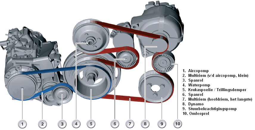
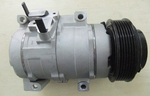
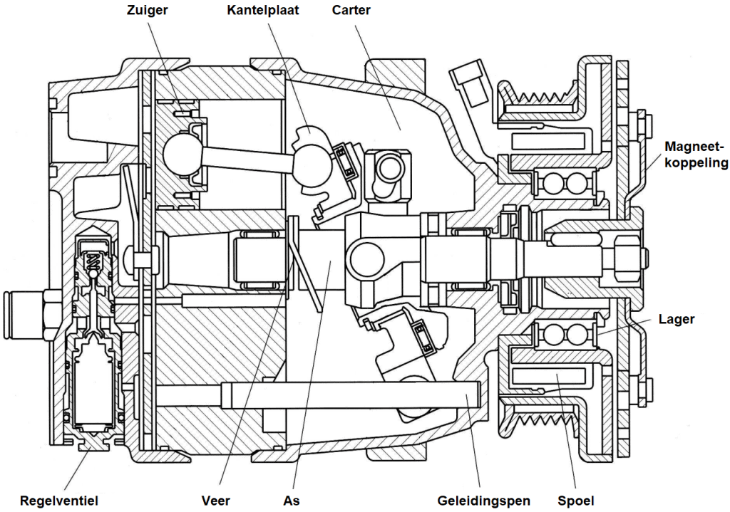
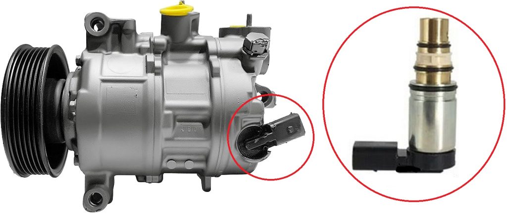
The compressor pumps the refrigerant—gaseous refrigerant from the A/C—through the entire system. The pressure and temperature of the refrigerant increase when it leaves the compressor. There are different types of compressors that can be used for air conditioning. In modern automotive A/C systems, reciprocating compressors are used. “Reciprocating” means that the parts in the compressor move back and forth. The operation of these compressors can be compared to that of a piston engine. Reciprocating compressors also come in two types: the crank type and the swash plate compressor. In modern cars, swash plate compressors are used, which in turn are divided into two types: the swash plate compressor with fixed displacement and the variable-displacement version. The A/C compressor, like the alternator and the power steering pump, is driven on internal combustion engines by the serpentine belt (see the image below). In hybrid and fully electric vehicles, we find electric A/C compressors. An electric motor is powered by the HV system and drives the compressor.
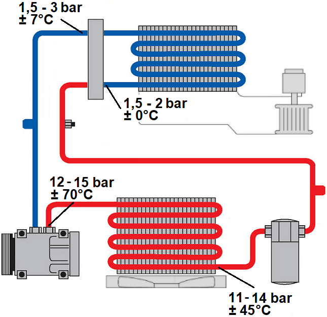
The A/C compressor draws in gaseous refrigerant from the evaporator, keeping the pressure in the evaporator low and contributing to evaporation of the refrigerant, even at low temperatures. The compressor compresses the gaseous refrigerant, which results in the transition from low to high pressure. This pressure increase and temperature rise cause the refrigerant to change from gaseous to liquid.
The pressure delivered by the A/C compressor is influenced by various factors, including:
- Engine speed (on internal combustion engines);
- The type and amount of refrigerant;
- The temperature of the refrigerant;
- The type and design of the A/C compressor, which determines capacity;
- The adjustment of the magnetic clutch;
- Ambient temperature.
After compression, the refrigerant leaves the compressor at a temperature of about 70 degrees Celsius. This temperature is then reduced in the condenser.
In the following paragraphs, different versions of A/C compressors are discussed, which may or may not be used in the automotive industry.
Vane / sliding-vane pump:
This pump is rarely used in a car’s A/C system. However, it can be used in specific refrigeration systems for various products.
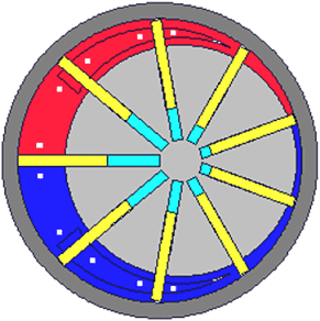
Operation: The (gray) disk rotates to the right, clockwise. The yellow plungers are pressed against the wall by centrifugal force, separating the different chambers from each other. At the bottom right, the refrigerant flows in and follows its path to the small blue space. Due to the rotation, this space becomes larger, which creates a vacuum. The pump continues to rotate, moving the refrigerant into the red section. Here, the chamber volume becomes smaller and smaller, putting the refrigerant under pressure (compressing it). At the end of the red chamber is the outlet valve, through which the refrigerant is forced out.
Piston compressor (reciprocating, crank type):
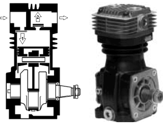
This pump, like the vane / sliding-vane pump, is rarely used in a car’s A/C system. However, it can also be used in specific refrigeration systems for various products. The image below shows a piston compressor, where 1 stands for the inlet valve and 2 for the outlet valve. The motion of the piston and crankshaft is comparable to that of a conventional Otto or diesel engine.
Operation: The piston moves from TDC (Top Dead Center) to BDC (Bottom Dead Center) (from top to bottom), causing inlet valve 1 to open. Due to vacuum, the refrigerant is drawn into the cylinder. The piston then moves from BDC to TDC and presses the inlet valve back against its seat. The upward movement also lifts outlet valve 2 off its seat. The refrigerant can now leave the cylinder. The outlet valve closes again. The cycle then starts again.
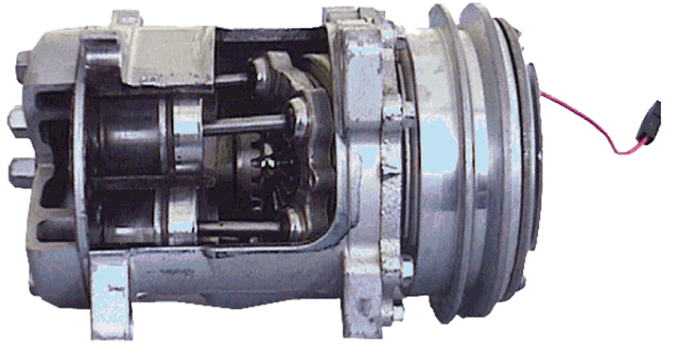
Swash plate compressor introduction:
Swash plate compressors, also known as wobble plate compressors, are almost always used in automotive A/C systems. They fall under the “reciprocating” category because their moving parts go up and down.
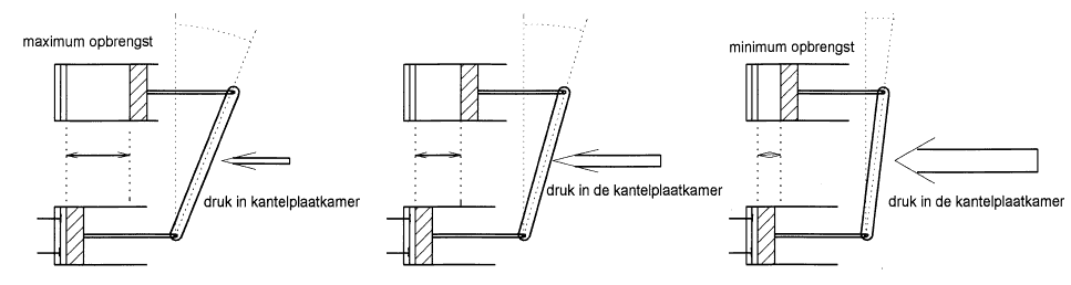
In the illustration we see a line drawing and cross-section of a swash plate compressor. The piston makes a horizontal stroke, which is determined by the angle of the swash plate. In this image the plate is tilted to the maximum, which means the piston can make a maximum horizontal movement (indicated by the red compression space in the cylinder). In the three drawings (from top to bottom) we see a complete compression stroke of a piston as a result of the rotation of the swash plate.
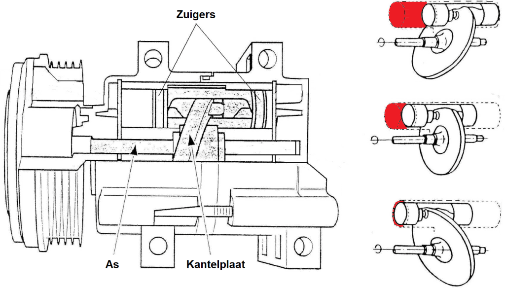
In this situation the pump delivers maximum output because the swash plate has produced maximum stroke. If lower output is desired because the pressure becomes too high and—due to too much refrigerant—freezing of the evaporator can occur, then on a compressor with “fixed displacement” the magnetic clutch is disengaged, so the compressor is no longer driven. On a “variable-displacement” compressor, the plate is tilted less. The angle at which the plate tilts is smaller, so the piston stroke also becomes smaller. Fixed- and variable-displacement compressors are described later on the page.
Above each piston are 2 valves attached to a disc spring: the suction valve and the discharge valve. When the piston moves from TDC to BDC, it forces the refrigerant out past the discharge valve into the high-pressure line toward the condenser.
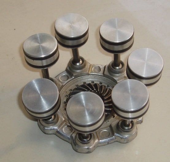
Swash plate compressors can have between 4 and 8 pistons/plungers and come in two versions: namely the fixed-displacement compressor and the variable-displacement version. These are described below.
Swash plate compressor with fixed displacement:
This compressor is driven by the engine’s serpentine belt and rotates synchronously with engine speed (between 600 and 6000 rpm). The magnetic clutch controls switching the compressor on and off, which will be explained further later.
When the compressor is switched on, the rotating swash plate moves the pistons up and down. Suction and discharge valves at each cylinder allow the pistons to draw in gas and move it under pressure to the high-pressure section of the system.
A fixed-displacement compressor moves a fixed volume per revolution. Output therefore depends on compressor speed, i.e., engine speed. To control output, the compressor is continuously switched on and off: switched on when pressure drops and switched off when pressure is too high. Especially on small engines, engagement can be felt as a “jolt” due to the power demand. Abrupt engagement causes higher mechanical load and disrupts control, resulting in variations in the cooled air temperature for occupants.
At excessively high engine speed and therefore increasing discharge pressure, more refrigerant flows through the evaporator. This slows cooling and can freeze the evaporator. In such cases, the magnetic clutch disengages due to the thermostat or pressure switch.
Swash plate compressor with variable displacement:
With this type of compressor, the angle of the swash plate is adjustable thanks to an adjustment mechanism. By setting the swash plate as upright/straight as possible, piston stroke is limited and output is minimal. On the other hand, by setting the swash plate as angled as possible, the pistons make a much larger stroke and output increases significantly. We see the following versions of the variable-displacement swash plate compressor:
- with internal control and magnetic clutch;
- external control with and without magnetic clutch.
Internal control and magnetic clutch:
The image shows how the position of the swash plate can affect piston stroke. A higher engine speed results in greater compressor output. This causes an increase in pressure throughout the system, which prompts the adjustment mechanism to increase the pressure in the swash plate chamber.
The increased pressure forces the swash plate to become more upright, reducing capacity. If output drops, the adjustment mechanism closes and the pressure in the swash plate chamber decreases. As a result, the plate tilts again, allowing the pistons to make a larger stroke. The greater the angle, the greater the stroke and the greater the output.
With an internal (mechanical) control system for adjusting the swash plate position in a variable-displacement A/C compressor, suction pressure is typically used to regulate the adjustment automatically. This system uses a pressure-actuated mechanism that responds to changes in the compressor’s suction pressure.
The control mechanism usually consists of one or more diaphragm or bellows chambers that are connected to the suction side of the compressor and to the swash plate drive shaft. If suction pressure changes, it causes movement in the diaphragm or bellows. This movement is then transferred to the mechanism that adjusts the angle of the swash plate.
- At higher suction pressures, such as when cooling demand increases, the pressure-actuated mechanism will adjust the swash plate angle. This results in a longer piston stroke and therefore higher compression of the refrigerant. This results in higher discharge pressure and greater cooling capacity.
- At lower suction pressures, the mechanism will reduce the swash plate angle, resulting in a shorter piston stroke and lower compression of the refrigerant. This lowers discharge pressure and matches cooling capacity to the reduced cooling demand.
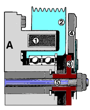
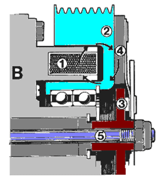
In a variable-displacement A/C compressor, a valve controls the connection between the crankcase (in the swash plate chamber) and both the high- and low-pressure sides of the compressor. The pressure on the low-pressure side is influenced by the measured suction pressure. Below, it is explained how the control valve works when output is increased and decreased.
Increasing output:
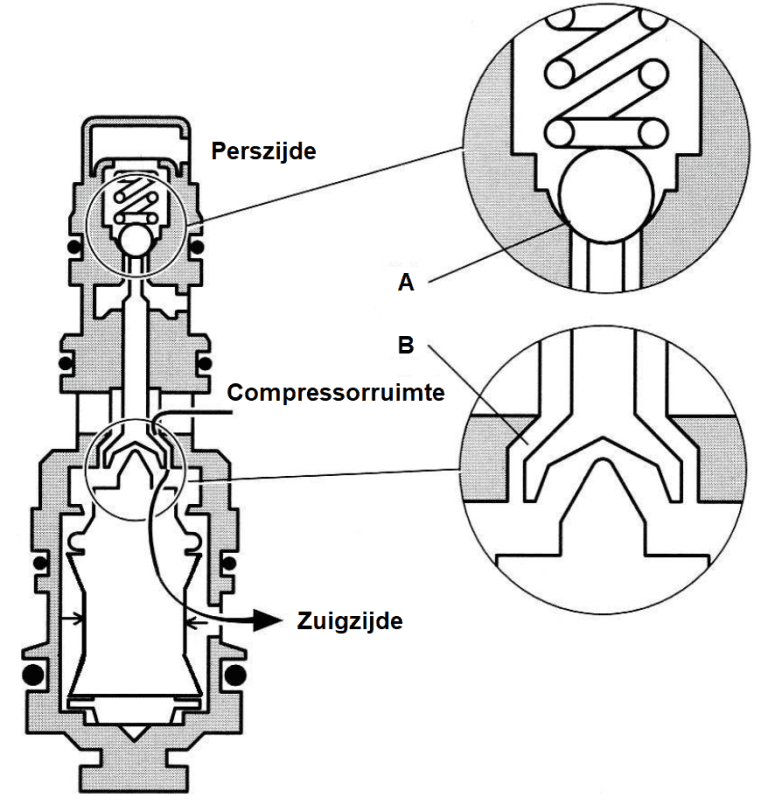
When cooling capacity decreases, temperature on the suction side rises and suction pressure increases. This suction pressure causes the elastic bellows to be compressed, making it smaller. When the bellows is compressed, ball valve A closes and valve B opens. This creates a connection to the crankcase. This allows the pressure in the swash plate chamber to escape to the low-pressure side (on the suction side), causing the swash plate to tilt more. This results in greater compressor output and an increase in cooling capacity.
Decreasing output:
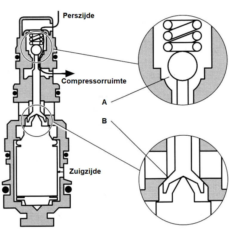
If cooling capacity increases, suction pressure decreases. Suction pressure becomes lower and the bellows increases in volume, causing opening B to close and ball valve A to open. This allows high-pressure gas to flow in and pass through ball valve A and the opening into the swash plate housing. This causes the swash plate to become more upright. As a result, pump output decreases and cooling capacity becomes smaller.
The control valve adjusts the pressure in the swash plate chamber. The resulting pressure difference relative to the pressure in the compression chambers leads to tilting of the swash plate, which affects pump output. Stroke is controlled by the pressure in the low-pressure section of the A/C system. Variable-displacement compressors usually do not have an evaporator thermostat switch. On these compressors, inlet pressure is kept at 2 bar.
External control, without electromagnetic clutch:
On a compressor with external control, an electromagnetic valve is used to regulate the pressure in the compressor housing. The electromagnetic valve is controlled by an ECU (the engine ECU or A/C ECU) via a PWM signal. However, suction pressure still plays a role in the control process. The A/C ECU receives signals such as the desired A/C mode (dehumidify, cool), the desired and actual temperature, and the outside temperature.
Based on this, the computer calculates the optimal setting for the control valve and thus the compressor output. If necessary, the suction pressure can also vary. In practice, suction pressure varies between 1.0 and 3.5 bar. A low suction pressure improves cooling capacity at low compressor speed. A higher-than-average suction pressure at low heat load results in more efficient operation and thus lower fuel consumption. The heavy electromagnetic clutch can now be omitted, saving about 1 kg. Usually, the clutch is equipped with a vibration damper and a slip mechanism.
A higher control current to the control valve shuts off the passage from the high-pressure chamber to the crankcase. The variable opening provides room to discharge the pressure-increasing leakage gas via the suction-pressure chamber. This equalizes the pressure in the crankcase (Pc) and the suction pressure Ps, causing the wobble plate to move into the position for maximum output.
Reducing the output is done by increasing the pressure in the crankcase. The control valve opens, creating a connection between the crankcase and the high-pressure chamber. The control valve has a bellows that is influenced by the suction pressure, which changes the set point. The control current to the control valve works together with the bellows setting. A small variable opening allows a limited flow of refrigerant into the suction-pressure chamber.
Compressor lubrication:
Heat always develops in moving parts, and therefore they must be lubricated. In addition to its lubricating properties, the oil also provides sealing and noise damping. Initially, the compressor is filled with oil, and lubrication is provided via oil-mist lubrication. This oil mist also reaches the plungers and is then carried through the entire system with the refrigerant. During condensation, a mixture of refrigerant and a liquid oil mist forms. This oil mist is then drawn back in by the compressor.
Synthetic PAG (Polyalkylene glycol) oil is specially designed for the refrigerant R134a and must never be replaced with another type of oil. However, the different viscosities specified by manufacturers must be taken into account. Refer to the specifications for this.
Common PAG oils are:
- PAG 46 (lowest viscosity)
- PAG 100
- PAG 150 (highest viscosity)
- PAG oil with the YF additive for use with the refrigerant R1234YF, due to sensitivity to moisture in the system.
In addition to PAG oils, there are also mineral, PAO, and POE oils.
- Mineral oil was used in old R12 systems.
- PAO oil (PolyAlphaOlefin) is fully synthetic and not hygroscopic. This is in contrast to PAG oil, which is strongly hygroscopic.
- POE oil (Polyester) is used in electric A/C compressors of HV vehicles. If the wrong oil (PAG) is used, the insulated lacquer layer on the copper wire of the electric motor is attacked.
When installing a new compressor, there is already oil (about 200 to 300 ml) in the compressor. The manufacturer specifies this oil quantity in the documentation.
Without evacuating the system, it is not really possible to determine how much refrigerant and oil are present in the system. In the case of a repair, for example after replacing a condenser, a small amount of oil will be lost. The manufacturer usually indicates how the distribution in the system is. In general, we can use this distribution:
• compressor approx. 50%
• condenser approx. 10%
• flexible suction line approx. 10%
• evaporator approx. 20%
• filter/drier approx. 10%
When the system is switched on for the first time, the oil is distributed throughout the system. If the system is later emptied and then refilled, for example when replacing another component or during maintenance, the oil can be added to the refrigerant via the charging station. It is essential to ensure that not too much oil ends up in the compressor. The result of too much oil in the system can be that the compressor hydro-locks. In A/C systems with a capillary tube, an accumulator is mounted just before the compressor, which continuously adjusts the amount of oil to the amount of refrigerant (see the page about the accumulator).
Electromagnetic clutch:
The pulley of the A/C compressor is continuously driven by the serpentine belt. On swash-plate compressors with fixed displacement and some with variable displacement, the electromagnetic clutch controls switching the A/C compressor on and off. When the compressor is switched on, an electromagnet (1) in the clutch is activated. This causes the magnet to pull in the spring-mounted clutch plate (4), creating a solid connection between the pulley and the compressor. When the air conditioning is switched off, the electromagnet is no longer activated and its magnetic effect stops. The spring of the clutch plate pushes it away from the compressor. The pulley now continues to rotate with the serpentine belt, while the compressor (internally) is stationary.
Switching on the air conditioning is most favorable when the engine is running at low rpm, such as with the clutch depressed or when the engine is idling. This minimizes wear on the electromagnetic clutch. For example, if the air conditioning is switched on at 4500 rpm, the electromagnet will engage the clutch and there will be a large difference in speed between the stationary compressor and the rotating pulley. This can cause slip, leading to increased wear.
Noises:
A few characteristic noises can occur:
Clunking noise when switching on: A loud clunking noise when switching on the compressor may indicate a possible adjustment issue with the electromagnetic clutch. Depending on the type of compressor, this adjustment can reduce the air gap and minimize the noise.
Humming noise from the A/C compressor: A humming noise indicates a defect in the compressor, or possibly a shortage of refrigerant and oil in the system. Consult an A/C specialist to have the system checked, evacuated, and refilled with the correct amount of refrigerant and oil.
Rattling noise from the A/C compressor: A rattling noise can also indicate a compressor defect. Check that the electromagnetic clutch is securely attached to the compressor to prevent the center bolt from loosening.
Buzzing noise linked to engine speed: A buzzing noise that is audible in the interior and follows engine speed indicates resonance or vibration. This can be caused by too low a refrigerant charge or by A/C lines resonating. If the refrigerant level is OK, a vibration-causing line can be identified by holding it while accelerating. Special vibration dampers, such as those available for specific issues like on MINI, can correct this type of vibration.
Related page: