Topics:
- Introduction
- Controlled and uncontrolled autogas systems
- Autogas and gas tank
- Filling connection
- Gas shut-off valve
- Petrol shut-off valve
- Switching from petrol to gas
- Operation of the vaporizer
- System with stepper motor with dry gas hose (AMS)
- Vapour-gas injection (VSI/EGI)
- Operation of the EGI vaporizer
- Liquid gas injection (LPi)
- Coupling block (LPi)
- Injectors (LPi)
Introduction:
Autogas is used worldwide on a small scale as fuel for passenger car engines. As of 2013, about 700,000 vehicles run on this fuel. This number may decrease because the road tax advantage for classic cars younger than 40 years has been scrapped. The tax rate for these older cars is now the same as for a younger car. When the autogas system is removed (and of course the car is converted back), people can once again make use of the tax advantage if the vehicle is between 26 and 40 years old.
Autogas is better for the environment than petrol or diesel fuels, for example. The exhaust gases are cleaner. The fuel itself is also cheaper per litre than petrol. Consumption with autogas is often slightly higher, but the break-even point is low. Engine power does drop slightly with autogas compared to petrol, with the exception of the LPi system. More about this is explained at the bottom of this page.
There are three different types of autogas systems. These systems are explained in detail on this page:
- System with a stepper motor in the dry gas hose (AMS) (single-point injection before the throttle valve)
- Vapour-gas injection (VSI/EGI) (multipoint injection at the intake valve)
- Liquid gas injection (LPi) (multipoint injection at the intake valve)
The terms G2 or G3 are often used:
G2 installations use a gas venturi system or a vapour-gas injection. A catalytic converter with a lambda sensor may be present on the car and the equipment may be the same as on a G3 installation. Despite this, they may not fall under the tax advantage of a G3 installation because the vehicle does not meet the ECE94-12 emission standards, or because the vehicle has not been tested by an accredited inspection authority. G3 installations use the control times of the petrol injectors that are calculated by the engine management system. These times are converted into control times for the gas injectors.
Controlled and uncontrolled autogas systems:
In old cars (classics) without an engine management system, i.e. without a catalytic converter and lambda control, an uncontrolled autogas system is used. This conventional system was used until 1990, because at that time environmental requirements became stricter. There were also more problems with backfires with the uncontrolled system. A controlled system, as is still used today, is equipped with an electronic control unit. With the help of the lambda sensor, a more accurate amount of gas can be injected. The catalytic converter converts harmful exhaust gases into less harmful ones.
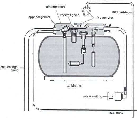
Autogas and gas tank:
The composition of autogas varies in summer between 30% propane and 70% butane, and in winter up to 70% propane and 30% butane. At a temperature of -10 degrees, butane no longer leaves the tank because the vapour pressure is then too low, so the percentage in winter must be lower than in summer. This is done automatically at the filling stations. If the car is driven very little, there is a chance that fuel problems will arise because the composition in the tank is still from a warmer period.
The liquid autogas is stored in the tank. The gas is under an operating pressure of a maximum of 2500 kPa (25 bar).
A tank with liquid autogas may never be filled to 100%, because otherwise there is insufficient space for the gas to expand when heated. The gas tank is designed so that it can only be filled to 80%. The liquid autogas leaves the tank via the electromagnetic outlet valve, which opens when the engine is started. The liquid autogas then flows via the line to the gas shut-off valve. More about this later on this page.
After manufacture of the tank, the manufacturing date is stamped into the tank. The tank is deemed to be in order for the next 10 years. Gas tanks are pressure tested at 3000 kPa (30 bar). The bursting pressure of a gas tank is 10,000 kPa (100 bar). Around the fittings, a gas-tight box is installed, called the fitting box. The fitting box is connected to the outside air by means of a vent hose. The purpose of the fitting box is to discharge any leakage gases present to the outside air in the event of a leak. These leakage gases must absolutely not enter the interior.
Gas tanks are attached to a steel subframe with tensioning straps. This steel subframe is bolted to the car body. Plastic strips are fitted between the tank and the tensioning straps for protection. The gas tank may not be attached to the bodywork in any other way!
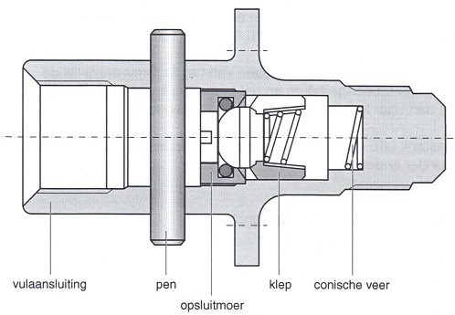
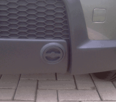
Filling connection:
The filling connection has a thread. An adapter can be screwed into it. This may be necessary when refuelling abroad. The external filling cap is fitted with a non-return valve that prevents gas from flowing back after filling. The pump at the filling station will push the gas through this filling connection under pressure. Via the filling connection, the gas flows through the filling hose to the gas tank.
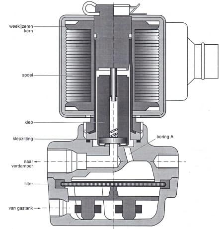
Gas shut-off valve:
The gas shut-off valve is mounted as close as possible to the vaporizer. The gas shut-off valve is energised when the ignition is switched on and the fuel selection switch is set to gas. The control unit controls this gas shut-off valve. The control is stopped when the engine stalls. The autogas that enters the gas shut-off valve from the gas tank flows through the filter. When the coil is not energised, the valve closes the passage to the vaporizer. The autogas then enters chamber “A” in the space around and above the valve. Because the autogas presses on the valve, the passage to the vaporizer is pressed firmly closed. As soon as the coil is energised, the soft iron core becomes magnetic. Due to the magnetism, the valve is pulled upwards. The passage to the vaporizer is now open, so that autogas can flow to the vaporizer. As soon as the engine is braked on the overrun, the gas shut-off valve temporarily closes the gas supply until the driver accelerates again.
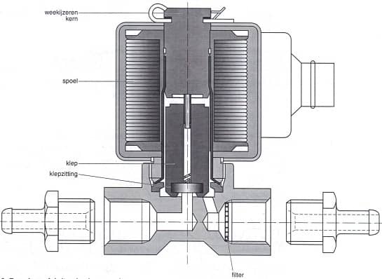
Petrol shut-off valve:
When running on gas, the petrol supply is shut off. At that moment the coil is not energised and the valve closes the passage. When switching back from gas to petrol, the coil is energised and the soft iron core becomes magnetic. As a result, the valve is pulled upwards, allowing the petrol to pass through.
Switching from petrol to gas:
If the engine is started on petrol and then switched over to gas, this switchover does not take place immediately. The engine temporarily runs on both fuels. This ensures a smooth transition from petrol to gas. This situation is called the “dual running time”.
The control unit determines how long the engine runs on both fuels at the same time. With a cold engine this will be longer than with a warm engine, because evaporation of a fuel is worse in cold outside air. After a few minutes (depending on the system and temperatures), the petrol supply is completely shut off via the petrol shut-off valve.
Operation of the vaporizer:
To make the operation of the vaporizer as clear as possible, the vaporizer in the image has been drawn as simply as possible. Later on this page, an explanation will be given about a real (EGI) vaporizer, which is considerably more complicated. Therefore, the simple vaporizer is explained first to make the basics clear.
The task of the vaporizer is to turn the liquid autogas in the tank into gaseous form. The liquid gas must be evaporated (hence the name vaporizer). Heat is needed to evaporate the liquid gas. This heat is extracted from the coolant. The coolant is heated by the engine and is therefore around 90 degrees when the engine is at operating temperature. It is important that the vaporizer warms up as quickly as possible, so the coolant is tapped before the thermostat. This can also be done at the heater circuit, because this supply line is also connected before the thermostat.
Because the vaporizer needs pure heat, it is logical that the engine must first be warmed up before the evaporation process can begin. That is also the reason why the engine cannot be started on gas straight away. At a cold start, the engine will run on petrol for the first few minutes before the system switches over to gas.
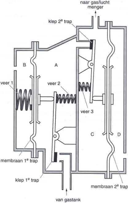
Theoretical operation of the vaporizer:
Chamber A is the first stage, chamber C is the chamber of the second stage.
In chambers B and D the reference pressure prevails, which in this case is the ambient air pressure.
Gas shut-off valve open, engine not running:
The liquid autogas flows from the gas tank past the valve of the first stage into chamber A. The autogas changes from the liquid form to a gaseous state here.
The autogas builds up pressure in chamber A. Due to this pressure, the diaphragm of the first stage is pushed to the left. Spring 1 is compressed, while spring 2 relaxes. When the pressure in chamber A is about 135 kPa, the diaphragm of the first stage has moved so far to the left that the valve of the first stage closes. No more autogas now flows into chamber A. Spring 3 ensures that in this condition the valve of the second stage remains closed.
Gas shut-off valve open, engine running:
When the engine is running, the intake air creates a vacuum at the outlet of the gas/air mixer. This vacuum propagates through the dry gas hose into chamber C (the second stage) of the vaporizer/pressure regulator. The reference pressure in chamber D now ensures that the diaphragm of the second stage moves to the left. Spring 3 is compressed and the valve of the second stage opens. Autogas now flows from chamber A to chamber C, and from there to the engine. Because autogas flows from chamber A to chamber C, the pressure in chamber A drops. The valve of the first stage will therefore open so that autogas from the tank again flows into chamber A. The autogas that flows past the valve of the second stage into chamber C builds up pressure in chamber C. Depending on the fuel demand of the engine, the diaphragm of the second stage will assume a certain position so that the opening of the valve of the second stage becomes larger or smaller. The greater the vacuum at the outlets of the gas/air mixer, the more autogas can flow to the engine. An equilibrium situation arises in which, depending on the vacuum at the outlets of the gas/air mixer, more or less gas flows past the valves of the first and second stage.
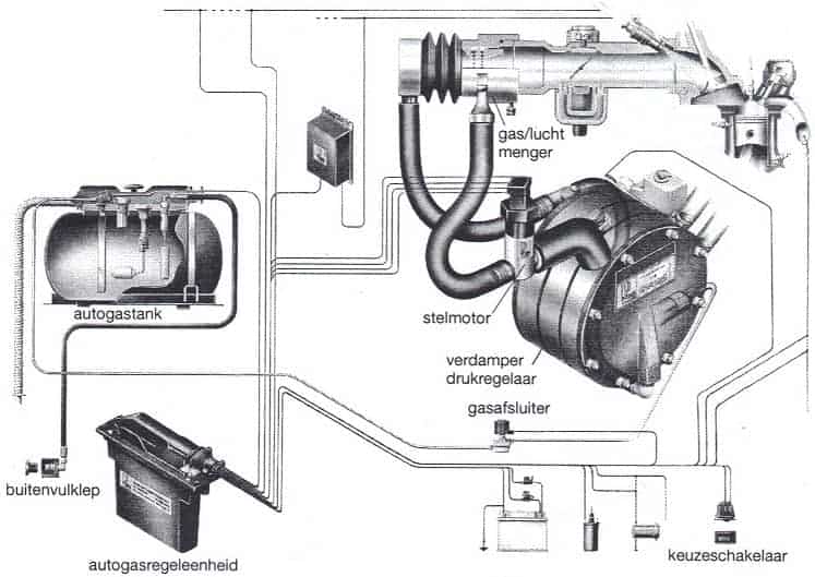
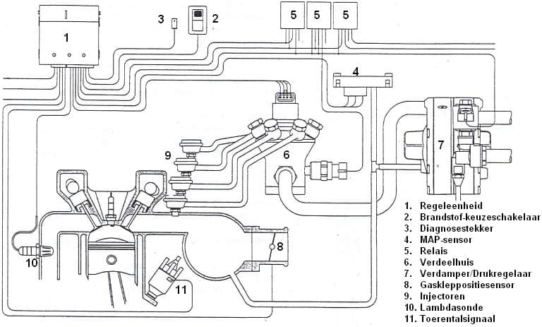
System with stepper motor with dry gas hose (AMS):
This is the AMS system from Vialle. The tank contains liquid autogas. The vaporizer/pressure regulator ensures that the gas evaporates when it leaves the tank and that the pressure is reduced. The quantity of gas leaving the vaporizer is controlled by the venturi in the gas/air mixer, which creates a vacuum. The greater the vacuum, the more autogas is drawn in. The vacuum depends on the engine speed and load (due to air speed). So if the engine revs higher, the amount of gas drawn in increases. However, this is not very precise. To deliver exactly the amount of gas the engine needs, fine adjustment is required. With the help of the measurement from the lambda sensor, the correct mixture ratio is calculated.
If too little gas is injected, the mixture is lean (lambda > 1). With too much gas, the mixture is too rich (lambda < 1). (The sign > means greater than, and < means less than). The lambda sensor will measure this in the exhaust gases. The engine management will therefore recognise the mixture as too rich or too lean and control the stepper motor. The stepper motor then makes the gas passage larger or smaller. This stepper motor is usually placed on the vaporizer. At a cold start, this stepper motor is in a neutral position and does not yet operate. The engine is still running in an “open loop” situation. This means that the lambda sensor signal is not yet used because cold start enrichment is still active. The disadvantage of the AMS system is that it is single-point injection. The gas is injected in front of the throttle valve and is distributed with the air over the various cylinders. Due to the large quantity of gas in the intake manifold, the chance of a backfire is very high.
Vapour-gas injection (VSI/EGI):
This is the Vapour Sequential Injection (VSI) or Electronic vapour Gas Injection (EGI). For convenience, it will now only be called EGI. The vapour-gas injection system is a multipoint injection system that is controlled by a control unit. Injection can now take place per cylinder instead of centrally in front of the throttle valve. This can be on a 4-cylinder engine, but also easily on a 6- or 8-cylinder. The gas is injected just in front of the intake valve. The chance of a backfire is now much smaller compared to the AMS system. With this type of gas installation, the engine must always be started on petrol. After a short time, the gas system will automatically be switched on.
The autogas leaves the vaporizer in gaseous form. The pressure has been reduced by the pressure regulator in the vaporizer. The gas then flows to the distribution block. The distribution block meters the amount of gas and distributes it over the injectors using the control slots. The injectors inject the vapour-form gas into the intake manifold, just in front of the intake valve.
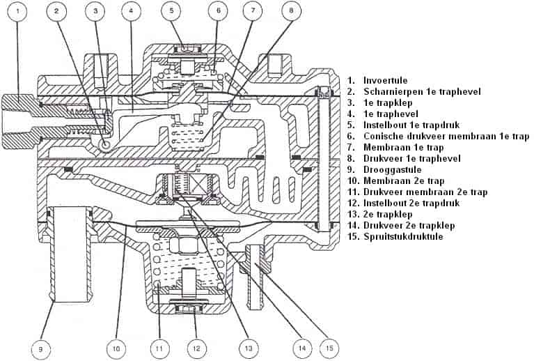
Operation of the EGI vaporizer:
The following text relates to the image below.
- Operation of the first stage:
In a pressureless state, spring 6 will push diaphragm 7 and the lever against spring 8 downwards, causing the valve of the first stage 3 to open.
When the gas enters at inlet connection 1, the gas will push diaphragm 7 upwards against spring 6. The lever 4 is now released, and spring 8 pushes the lever upwards. As a result, the valve of the first stage 3 closes.On the upper side of diaphragm 7 the vacuum of the engine prevails, making the pressure in the first stage also dependent on the engine vacuum. The pressure in the first stage can be adjusted by adjustment screw 5. Pressure first stage = Regulated pressure first stage – engine vacuum.
- Operation of the second stage:
The gas in the first stage can initially pass through the opening released by the valve of the second stage 13. The gas then presses against spring 11 and diaphragm 10, causing the second stage valve 13 to close due to spring 14.
On the underside of diaphragm 10 the vacuum of the engine prevails, making the pressure in the second stage dependent on the engine vacuum. The pressure in the second stage can be adjusted by adjustment screw 12.
Pressure second stage = Regulated pressure second stage – engine vacuum.
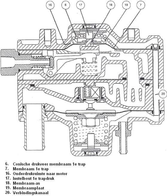
- Overpressure protection 1st stage:
When the pressure in the 1st stage becomes too high, diaphragm 7 together with diaphragm plate 19 will move upwards.
When the diaphragm shaft 18 comes up against the adjusting screw 17, the diaphragm shaft 18 can no longer move further up.
Diaphragm 7 continues to move upwards with diaphragm plate 19, causing diaphragm plate 19 to come to rest at the narrower section of diaphragm shaft 18. This creates an opening through which the gas from the 1st stage can go via chamber 16, channel 20 and manifold pressure nipple 15 to the engine’s intake manifold.
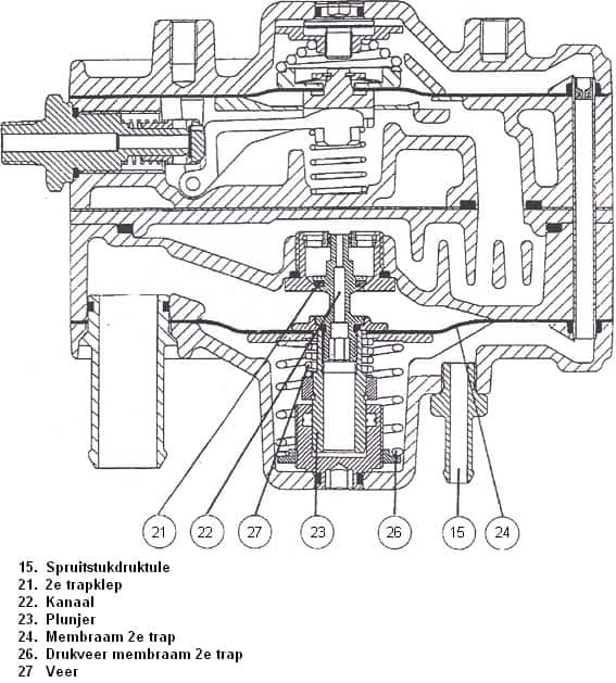
- Feedback:
The gas pressure from the 1st stage can reach underneath plunger 23 via channel 22.
This gas pressure therefore acts on the underside of plunger 23, opposite to the gas pressure from the 1st stage acting on the 2nd stage valve 21.
The gas pressure from the 1st stage on the 2nd stage valve 21 will now no longer influence the opening of the 2nd stage valve 21, because the gas pressure from the 1st stage under plunger 23 acts in the opposite direction.
Liquid gas injection (LPi)
LPi means: Liquid Propane injection. With liquid gas injection, autogas is injected as a liquid. There is therefore no vaporizer present in this system.
Because the liquid gas no longer needs to be vaporized, the engine can simply be started on gas. The petrol injection system is therefore effectively deactivated. The drawback is that the petrol injection system can become contaminated due to its limited use. It is therefore advisable to drive on petrol from time to time. The LPi system tries to mimic the petrol injection system as closely as possible. The liquid autogas is injected by the injectors onto the intake valve (exactly as with indirectly injected petrol engines).
The vaporizer and the gas/air mixer have been replaced by the distribution block and the injectors. A pump has been installed in the tank to circulate the liquid autogas. The liquid injection is controlled by the existing engine management system, which fully retains and uses its self-learning functions. The LPi system only uses the opening time signal of the petrol injector and translates this to autogas. Liquid autogas can be metered very accurately, better than gas in vapor form.
The LPi system follows the injection strategy of the petrol control unit. All options such as fuel cut-off during deceleration, rev limiter, full-load enrichment and lambda control are also carried out on autogas. With LPi the engine does not suffer any power loss. This is due to the absence of the air displacement effect, which remains present with vapor dosing. Because of the air displacement effect, the volumetric efficiency of the engine is reduced by approximately 6%. The liquid injection also provides a cooling effect due to the evaporation of the gas in the cylinder. This results in better volumetric efficiency, which in turn leads to improved engine performance. Fuel consumption is still higher than when running the same engine on petrol, because there is less combustion energy per kg of gas than in a kg of petrol.
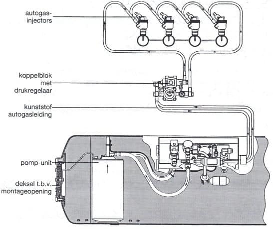
A high system pressure is required to inject the autogas in liquid form. The system pressure is supplied by the diaphragm pump in the tank. This pumps the autogas via the distribution block to the autogas injectors. The system pressure is regulated by the pressure regulator to 5 bar above the tank pressure.
Due to heating, vapor bubbles could form in the lines. Vapor is compressible and therefore cannot be injected accurately. By circulating the liquid autogas under pressure, heating and thus any vapor in the line is prevented. The lines are also made of plastic and insulated against heat.
There is also a filter mounted on the return line, which must retain any contamination and metal particles.
Distribution block (LPi):
The distribution block forms the connection between the tank and the injectors (see image below). An electromagnetic shut-off valve is integrated in the distribution block, which opens and closes simultaneously with the service valve on the tank. The pressure regulator (which was normally located at the vaporizer) and the pressure sensor are also mounted on the distribution block. The distribution block has 4 connections. The flexible high-pressure lines are attached to the distribution block with a banjo bolt. The connections must not be swapped because of the autogas flow direction. In case of a defect, the distribution block must be replaced as a complete unit, as it must definitely not be disassembled.
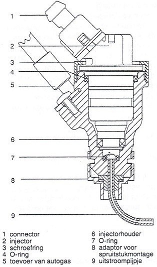
Injectors (LPi):
To inject the liquid autogas, “bottom-feed injectors” are used. This type of injector has the advantage (in contrast to top-feed injectors) that the heat from the injector coil does not cause heating of the autogas. Almost no reserve of autogas remains in the injector either. The injector coil has a resistance of 1.8 Ohm. A filter is installed in front of the gas inlet of the bottom-feed injector to prevent coarse assembly debris from entering the injector.
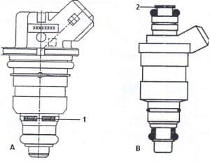
The injectors are placed in a universal injector holder. Sealing is provided by O-rings. The injector is held in place by a screwed ring. Depending on the position on the manifold, the gas is routed through the outlet pipes (see component 9 in the illustration).