Introduction:
Automotive Ethernet, BroadR-Reach and DoIP have been emerging within modern vehicle communication for several years now. Automotive Ethernet provides the physical and data link infrastructure for IP‑based communication with high data rates. BroadR-Reach formed the basis of today’s point‑to‑point Ethernet communication. DoIP is a diagnostic and programming transport protocol that enables diagnostic communication via IP over Automotive Ethernet.
In the first vehicles in which Ethernet was used, it was mainly deployed for diagnostics and infotainment, where higher data rates were required than were possible with the then common CAN bus systems. Due to the continuous increase in the number of ECUs, sensors and software functions, and the strongly growing data volumes from cameras, radar, central computing modules, infotainment and connectivity, the role of Ethernet has expanded further.
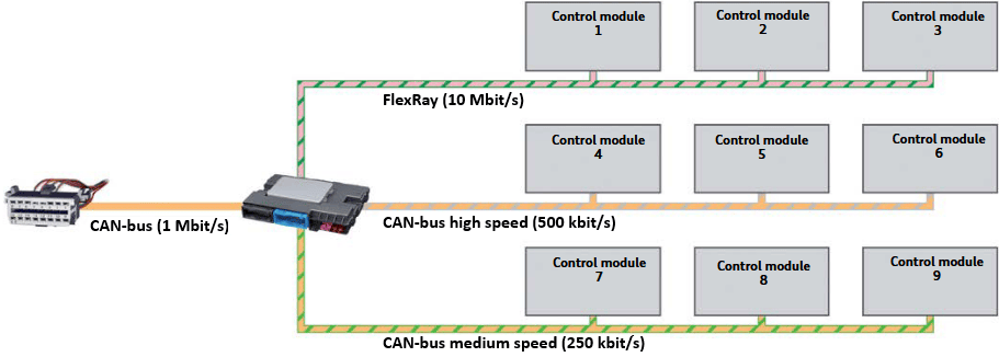
Networks such as CAN and LIN bus have been used in vehicles for a long time and remain a suitable means of communication as long as the amount of information being transmitted remains limited. For data‑rich functions, however, these networks fall short in available bandwidth. That is why Automotive Ethernet is increasingly being used in modern vehicle communication. In addition to Ethernet, these same vehicles still contain networks such as CAN, LIN bus and FlexRay.
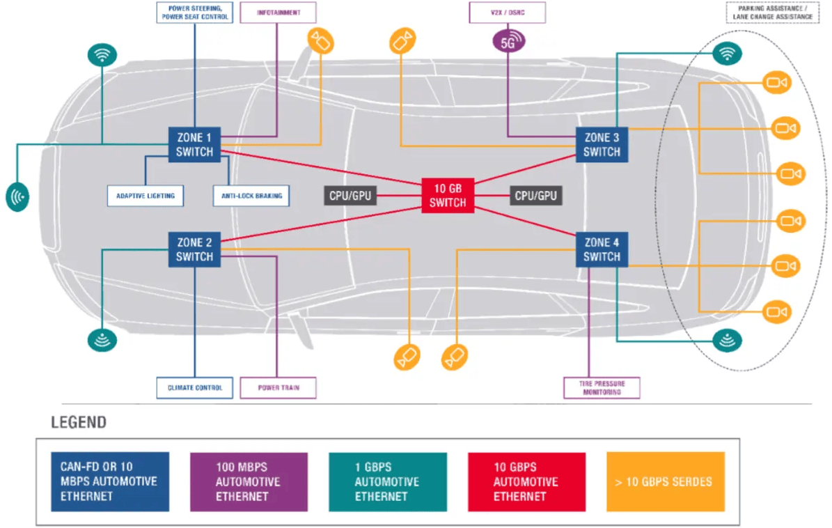
Automotive Ethernet topology:
Automotive Ethernet is based on the same protocol as the Ethernet we know from home, adapted for use in vehicles. The most commonly used physical layers for Automotive Ethernet are: 10, 100 and 1000 Mbit/s (Megabit per second). 1000 Mbit/s is equal to 1 Gbit/s (Gigabit per second). In diagrams this is indicated as 10BASE, 100BASE and 1000BASE. The word “BASE” means baseband signalling (baseband transmission); the entire cable is used for one Ethernet data connection. This section explains the topology and the following sections cover the specific properties per data rate.
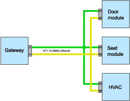
The topology of 10BASE-T1S, which has a bandwidth of 10 Megabit per second. ECUs in vehicles that are often connected via 10BASE-T1S are ECUs with a low to medium data demand that are located close to sensors and actuators and do not need a continuous high data stream, such as the door electronics, seat module or climate control.
Multiple ECUs are connected in parallel to the single twisted pair wiring, comparable to the topology of CAN bus and CAN‑FD. The length of the bus and the maximum branches (stubs) are limited in order to prevent reflections and signal distortion. Therefore, specific guidelines apply to cable length, branch length and termination, similar to those for other bus systems.
Because all ECUs share the same medium, only one ECU can transmit at a time. Access to the bus is not controlled by arbitration as with CAN, but by Physical Layer Collision Avoidance. Each ECU is assigned a fixed time slot in which it may transmit. This results in predictable and collision‑free communication on the shared bus, despite the use of Ethernet frames.
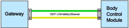
The topology of 100BASE and 1000BASE is characterised by the fact that a maximum of two ECUs communicate with each other via twisted pair Ethernet wires. This means: there is one ECU at one end and one ECU at the other end of a wire pair. There are no nodes added that connect other ECUs to this network, as we see with 10BASE Ethernet and CAN bus. In the literature we often see “module to module communication” or “ECU to ECU communication”. This refers to the topology described in this section.
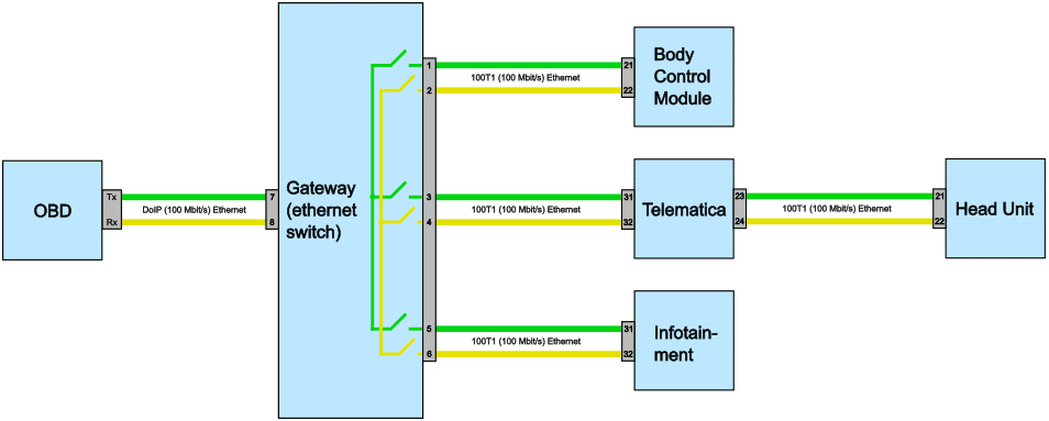
The ECUs of 100BASE and 1000BASE that are therefore not directly connected to each other via Ethernet can still communicate with each other through an Ethernet switch. The switch can connect two (sub)networks as soon as communication between them is required. Example: in the figure below, the “Body Control Module” can communicate with the “Infotainment module” via the Ethernet switch in the gateway.
Switches are often integrated into gateways or central computing modules. The physical switches are in reality MOSFETs that can be switched on and off by the electronics.
10BASE-T1S (10 Mbit/s)
This variant is used for Ethernet communication with sensors and actuators and is applied as an alternative or supplement to CAN and CAN FD networks. The technology was developed for use in the lower speed domain of vehicles and uses a multidrop bus structure, in which multiple ECUs, sensors and actuators are connected to one shared twisted pair. As a result, no classic Ethernet switch is required per node and the wiring harness can be made simpler and lighter.
Because multiple participants share the same transmission medium, 10BASE-T1S operates in half‑duplex. This means that transmitting and receiving do not take place simultaneously, but alternate. To prevent collisions on the bus, Physical Layer Collision Avoidance is used. Each ECU is assigned a fixed time slot in which it may transmit. Only the ECU with the active time slot may place data on the bus. Other ECUs listen. This prevents collisions and no message needs to be aborted or retransmitted. This differs from CAN bus, where the priority of messages is determined using arbitration.
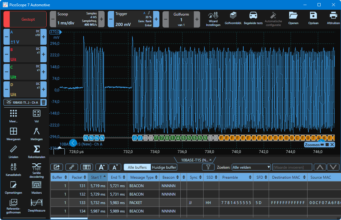
The oscilloscope image below shows the signal pattern of 10BASE Ethernet, which was measured by means of a differential measurement on both Ethernet wires on one measurement channel. With the Pico Automotive software the signal can be decoded. Characteristic of the 10BASE signal pattern:
- The data rate is approximately 10 Mbit/s with a bit time of about 100 ns per bit;
- In idle the signal voltage is approximately 0 volts;
- The amplitude of the signal is approximately 300 mV positive and 300 mV negative (600 mV difference);
- Beacon frames: these are used for synchronisation, similar to what the “sync field” does on LIN bus. This is the first block where “N N N N” is shown in the decoding.
- Packet frames: this is the message that is transmitted. This is the sequence that is labelled from J to F in the decoding. After the F, F is mentioned a number of times more, after which the data and the end of the message follow.
Below the oscilloscope image, the section from J to F is zoomed in. In the subsequent screenshots this part of the signal is zoomed in further, which also clearly shows what J and F stand for.
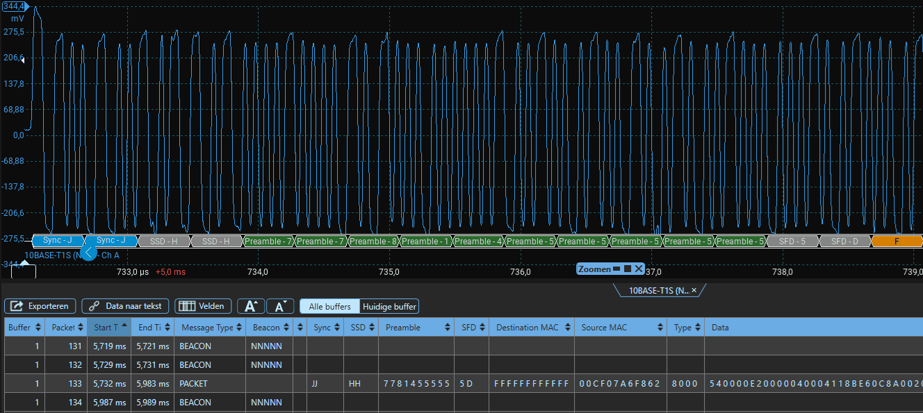
The oscilloscope image below is a zoomed‑in part of the above image (from J to F). Due to the zooming, the beginning of the packet is partially visible. In the decoding we see the following parts:
- Preamble (7781455555): this is the synchronisation between transmitter and receiver;
- SFD (Start Frame Delimiter, 5D): this is the beginning of the frame;
- Destination MAC (FFFFFFFFFFFF): broadcast -> every node may receive this frame.
The first F of the Destination MAC can be seen on the right side of the screenshot. The next screenshot shows the data starting from the last F of the Destination MAC.
After the last F of the Destination MAC, the message continues. This can be seen in the screenshot below:
- Source MAC (00CF07A6F862): here is the identifier of the ECU that sends the message;
- Type (EthernetType, 8000): IPv4 (typical for DoIP);
- Data: starting with 540000E20000040004118BE60C8A0020.
The data is so long that it cannot possibly fit into a single screenshot.
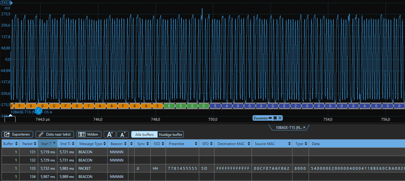
The screenshots above with their explanations covered the first part of the Ethernet signal. Below, the complete signal is shown. In the decoding, the orange and green sections with the Preamble, Destination and Source MAC can just be seen on the left. Then the blue/purple section of the decoding begins: this is where the data starts. In the screenshot above the data begins with 540000E2000004000. The total amount of data is estimated to be about two hundred times larger.
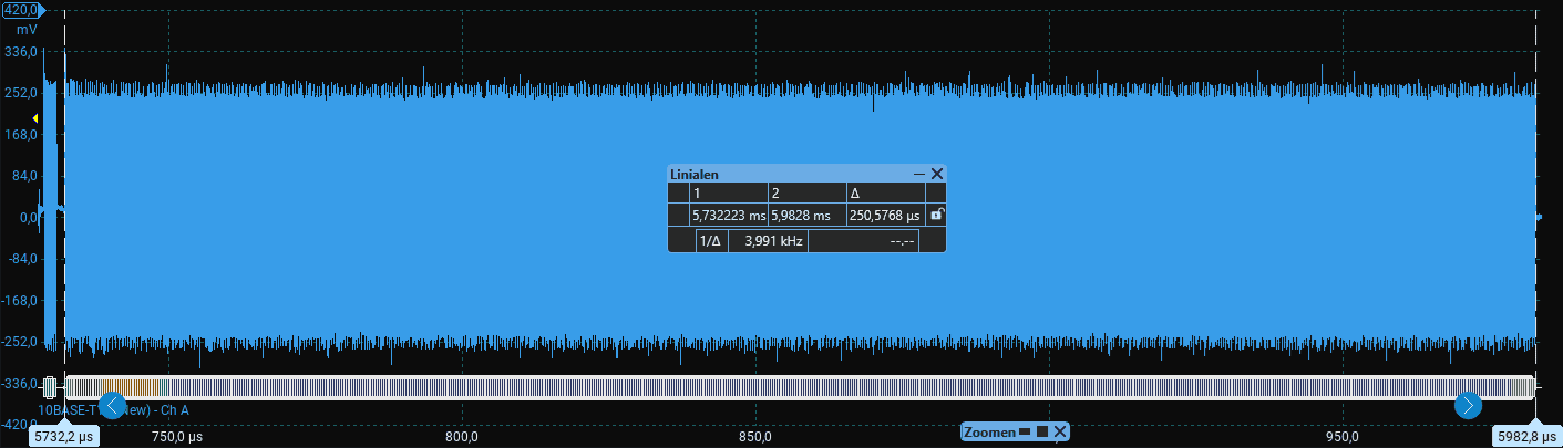
The screenshot below shows the end of the message, from the last data block up to the ESD (End of Stream Delimiter), with the FCS (Frame Check Sequence) in between, which, just like the CRC (cyclic redundancy check of CAN bus), sends along a calculation as a check.
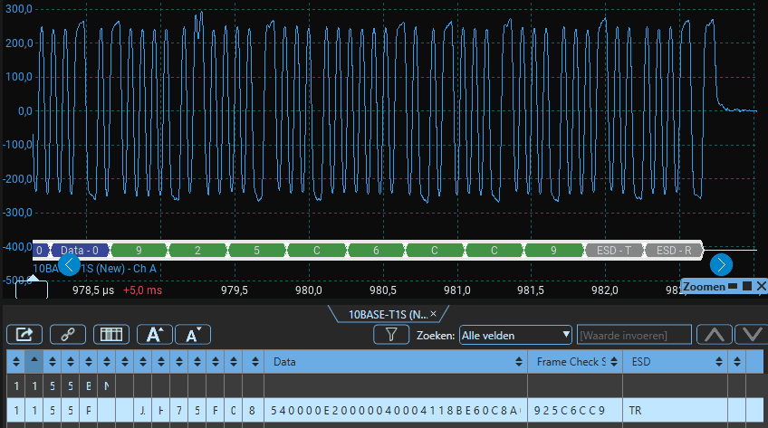
Finally, about the 10BASE Ethernet signal trace: the complete message between the rulers in the screenshot below lasts about 250 microseconds (0.00025 seconds). In that period, only the first 5% of the message has been explained in the three previous screenshots, followed by a huge amount of data that is transmitted in a very short time. This is an important characteristic of Ethernet: many messages within a short time thanks to a large bandwidth. Although this illustrates that an enormous amount of data can be transmitted in a short time, 10BASE is the slowest Ethernet we may encounter in vehicles, but it is the one we can still measure and decode properly with a PicoScope Automotive oscilloscope. Unfortunately, the Automotive scope has too low a sample rate to measure the faster systems accurately.
100BASE-T1 (100 Mbit/s)
100BASE-T1 has a speed of 100 megabits per second and uses point-to-point communication over an unshielded twisted pair. The connection always consists of exactly two ECUs that communicate exclusively with each other. As a result, no consideration needs to be given to other ECUs sharing the same transmission medium. The connection is full duplex, which means communication can take place in both directions simultaneously. In 100BASE there is no recessive state where no data is transmitted: the link remains continuously active.
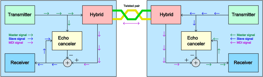
The image below shows how full-duplex communication over a single twisted pair is made technically possible. Both ECUs transmit and receive simultaneously via the same Ethernet wiring. The transmit signal from the transmitter is placed on the twisted pair via the hybrid, but part of that same signal leaks directly back into its own receive path. This leaked-back signal is referred to as the echo. At the same time, the transmit signal from the other ECU arrives via the same pair of wires. The signals on the Ethernet wires therefore always contain a combination of the ECU’s own transmit signal, its echo, and the receive signal from the other side.
The receiver measures this combined MDI signal and cannot directly distinguish it without additional processing. That is why the PHY contains an echo canceller. This echo canceller receives the ECU’s own transmit signal from the transmitter and calculates the echo signal, which is then subtracted from the measured MDI signal. What remains is the transmitted signal from the other ECU, which can then be reliably decoded.
Because this process takes place continuously, both ECUs can transmit and receive permanently without waiting times or time slots.
These characteristics make 100BASE-T1 suitable for applications with fast, continuous data streams, such as camera data, infotainment, and communication between gateways and central computing modules. The difference from 10BASE is that in that variant transmitting and receiving alternate on a shared medium, whereas with 100BASE both directions are active simultaneously via a point-to-point connection.
100BASE is used in systems such as cameras, telematics modules, gateways, and infotainment links, where IP communication and higher bandwidth are required, but where the very high data rate of 1000BASE (1 Gbit/s) is not yet necessary.
Below is a measurement of the 100BASE Ethernet signal trace. Just as with CAN bus, the signal of channels A and B moves in opposite directions: when the voltage of channel A becomes high, the voltage of channel B becomes low, and vice versa. The ECUs determine the voltage difference between the two signals.
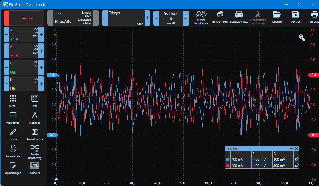
The 100BASE signal trace is not clean. There are no clear data blocks visible as we can measure with 10BASE, and serial decoding is not possible. This is because the refresh rate of the Automotive oscilloscope is too low. To obtain a clean signal trace and to use the decode function, an oscilloscope from a higher price range must be used (from approx. €5000).
1000BASE-T1 (1000 Mbit/s = 1 Gbit/s)
1000BASE-T1, like 100BASE-T1, uses an unshielded twisted pair with differential signal transmission. The connection is also point-to-point and full duplex, allowing simultaneous transmitting and receiving between two ECUs while the echo is filtered out. This variant is used in systems where 100BASE-T1 does not provide enough bandwidth, such as high-resolution cameras for ADAS, radar and lidar systems, central computing modules, video streams, and aggregated sensor data.
Due to the higher data rate and associated signal frequencies, 1000BASE-T1 imposes stricter requirements on wiring, connectors, and installation than 100BASE-T1. Deviations in twisting, increased contact resistance, or incorrect repairs have a quicker impact on signal quality and can lead to unstable communication. For this reason, manufacturers often apply stricter specifications for harness design, routing, and repair for 1000BASE-T1.
BroadR-Reach:
BroadR-Reach was developed by Broadcom as an automotive Ethernet physical layer for 100 Mbit/s full-duplex communication over a single unshielded twisted pair. Later this technology was also referred to as OPEN Alliance BroadR-Reach (OABR). BroadR-Reach was originally owned by Broadcom and not an open standard. As a result, its use was initially mainly tied to Broadcom hardware. Ultimately, BroadR-Reach served as the technical basis for the open 100BASE-T1 standard, defined in IEEE 802.3bw-2015.
BroadR-Reach therefore forms the origin of the 100BASE-T1 connection and is no longer used today as a separate technology. The term BroadR-Reach still appears in documentation and vehicle descriptions of older vehicles, where Ethernet connections are used that are technically equivalent to the current 100BASE-T1 standard.
DoIP (Diagnostics over Internet Protocol):
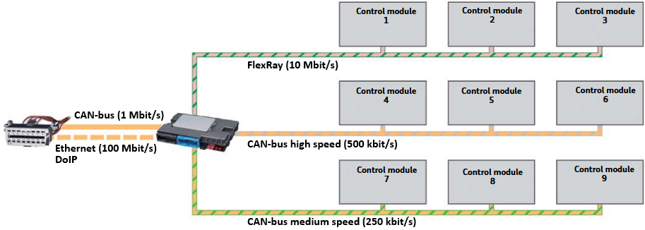
DoIP (pronounced “doo-ip”, with IP pronounced as in internet protocol) stands for Diagnostics over Internet Protocol. DoIP is a diagnostic and programming protocol that uses IP communication over automotive Ethernet. With DoIP, diagnostic data is transmitted via Ethernet. As a result, data transfer is much faster than with CAN bus. If a car with DoIP is connected via the OBD, many scan tools will ask whether you want to read out via CAN or via DoIP.
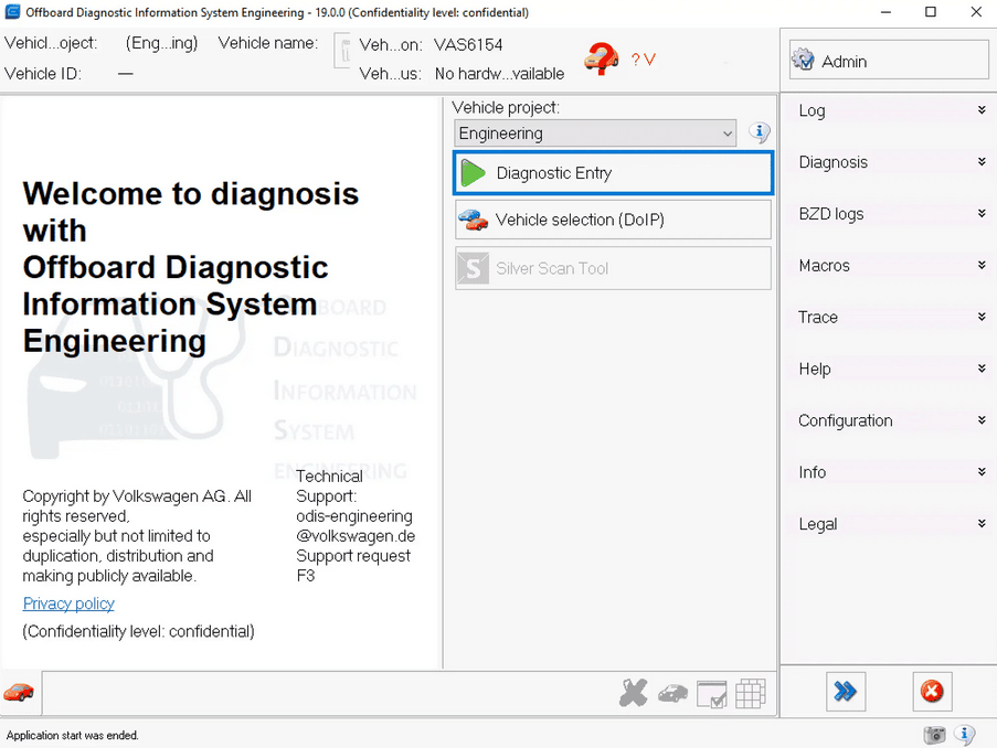
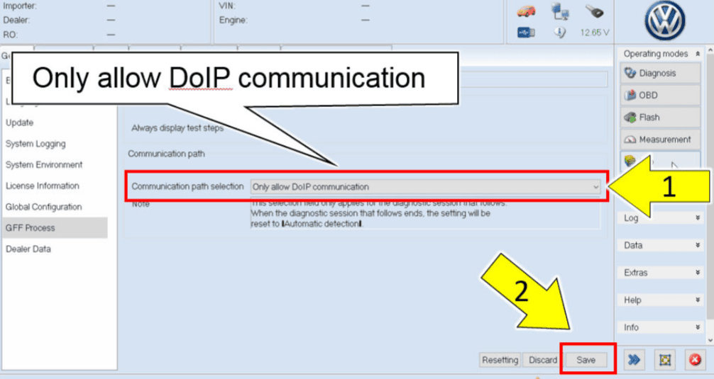
The main functional reason for using DoIP is the significantly higher data rate and thus also the communication speed compared with diagnostics via CAN. This is particularly relevant when programming and flashing ECUs and when processing larger data sets. In practice, this is noticeable in shorter programming times and faster loading times while reading vehicles with a lot of software and a large number of ECUs. When programming ECUs, it is sometimes necessary to manually switch from CAN to DoIP. In the images below there are screenshots from ODIS (VAG) showing an option for DoIP before reading out, and the manual setting to flash via DoIP.
In modern vehicles, DoIP communication usually takes place via a central gateway. The diagnostic tool communicates via an Ethernet connection with this gateway, which forwards the data traffic via internal switch functionality to the correct ECUs. DoIP is not always active by default. A wake-up or activation condition is often required before communication can be established. For diagnostics this is an important point of attention: the absence of DoIP communication does not necessarily indicate a physical fault but may also mean that the activation or session conditions have not been met.
Wake-up line for DoIP:
The wake-up line is needed to bring ECUs and the Ethernet network out of a sleep state before IP and DoIP communication are possible. Without wake-up, the Ethernet connection is often not active. Modern vehicles power down ECUs and networks to save energy. This is called “sleep mode”. Automotive Ethernet ECUs, switches and gateways are not active at IP level in this state, often not even at PHY level, and are therefore not visible for DoIP or diagnostics during sleep mode. That is why a separate wake-up mechanism is necessary.
The wake-up line is a simple electrical signal, usually a 12-volt or 5-volt signal depending on the vehicle design, with which an ECU or gateway receives a command to wake up. As soon as the wake-up becomes active, the ECU leaves sleep mode, the Ethernet PHY is switched on and IP communication becomes active. Only then can DoIP communication take place. Without this activation, the ECU remains silent, even when the Ethernet cable is correctly connected.
In practice, the wake-up can be activated by the ignition switch, opening a door, connecting a diagnostic tool, a separate wake-up pin in the OBD connector, or a CAN message that activates a gateway. For DoIP via the OBD connector, a specific pin is often used to wake the central gateway or DoIP ECU.
DoIP always requires an active IP connection. Therefore, in practice, the rule is: no wake-up means no Ethernet link, no Ethernet link means no IP communication, and without IP, DoIP is not possible. This is an important point of attention during fault diagnosis.
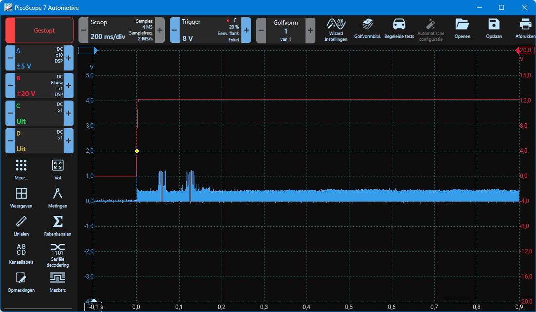
In the oscilloscope image below, the wake-up line (channel B) can be seen rising from 0 to approximately 12 volts at t = 0 s. At the moment the wake-up line is activated, communication on the Ethernet line starts. The result of this is visible on measurement channel A.
Power over Data Lines (PoDL)
In automotive Ethernet, in addition to data communication, power is increasingly transmitted over the same connection. This principle is referred to as Power over Data Lines. Here, supply voltage and data signals are combined over a single twisted pair, making additional power wires unnecessary.
This technique is comparable to PoE (Power over Ethernet) in home networks, where access points do not need a separate power cable in addition to a UTP cable.
PoDL is especially relevant for sensors and peripheral devices such as cameras, radar and lidar units, and compact ECUs. By combining power and data over a single connection, the wiring harness can be made lighter, thinner, and simpler. This results in benefits in terms of weight, cost, and installation.
The power is added to the Ethernet connection via special injectors so that the data signals are not disturbed. On the receiving side, the power is again separated from the data signal and used to supply energy to the connected module. The exact voltage and power levels are defined in standards and differ per application.
In diagnostics and repair, PoDL is an important point of attention. A fault in an Ethernet connection can lead to both data communication problems and the complete shutdown of a connected ECU due to missing power. As a result, it is not always immediately clear whether an error is caused by a data problem or a power problem. Measurements must also take into account the presence of supply voltage on the data line.