Topics:
Control units:
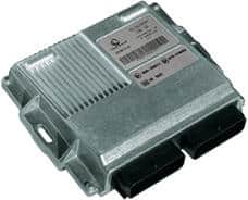
Modern cars contain many different control units. These control units each have their own function; the engine control unit receives information from all sensors in the engine bay and controls the actuators. The image on the right shows an engine control unit. An engine control unit is also referred to as an Electronic Control Unit (ECU).
This engine control unit has two connectors attached, often with more than 100 separate wires. Each wire has its own function; for example, information from the coolant temperature sensor enters on pin number 6, and via pin 81 the ECU controls the fuel injector of cylinder 1. All sensors in the engine compartment send their own information to the ECU. In the ECU, this information is processed by the engine management system in a so‑called map. The image below shows an example of this:
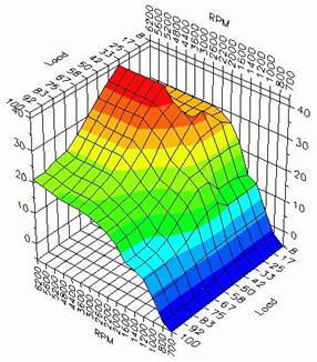
In the map, the data from the sensors is stored, such as the temperature of the outside air and the coolant, the position of the accelerator pedal, the turbo pressure, values from the lambda sensors, the engine speed, etc. Based on this data, the ECU determines at what moment the injector must open and how long it remains open (the longer it stays open, the more fuel is injected), but also the ignition timing, the control of the turbo, etc.
Because, among other things, the injection quantity, the ignition and the turbo pressure all depend on the engine speed and the load, it is very important that the ECU processes this data correctly.
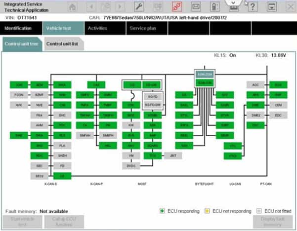
In a modern car there are often dozens of separate control units. The image shows a screenshot from a BMW diagnostic computer.
This screen is from a 2007 BMW 7 Series. Each green and grey block represents one control unit. So in total there are no fewer than 76 control units. The black lines indicate the cables that connect the control units. These cables include CAN bus cables. BMW uses its own designations for the different networks (K-CAN-S, K-CAN-P, BYTE-FLIGHT, LO-CAN, PT-CAN). Each network has its own speed and they are interconnected with a Gateway.
In the comfort network, all control units related to the interior and bodywork of the car are interconnected with CAN bus wires. This is called CAN-B (comfort bus). The image below shows which control units are all classed under “comfort”.
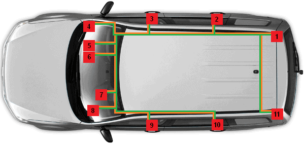
1. Control unit for towbar system
2. Right rear door control unit
3. Right front door control unit
4. Gateway
5. Comfort control unit
6. Alarm system control unit
7. Instrument cluster
8. Steering column electronics control unit
9. Left front door control unit
10. Left rear door control unit
11. Park Distance Control unit
The different control units can be mounted anywhere in the car; in the dashboard, in the doors, in the tailgate, above the headlining, you name it. The technician can look up the location of the relevant control unit in the workshop documentation or sometimes even in the diagnostic equipment. In this example only a small number of control units is shown. In reality there can be dozens.
In addition to the comfort bus (CAN-B) in the example, there is also a drive train bus (CAN-C). All communication from the engine to the wheels takes place via the drive train bus. An important difference between these two buses is the speed: CAN-B operates at a speed of up to 125 kbit per second and CAN-C at up to 1 Mbit per second. The speed at which the electric seat adjustment is controlled (CAN-B) does not need to be as high as the communication between safety systems of the Anti-lock Braking System (ABS).
Besides the different CAN bus systems with different speeds, there are also other network systems to allow control units to communicate with each other, such as LIN bus and MOST bus. To be able to connect these networks to each other, a Gateway is used. Without this gateway, the control units of, for example, the CAN-A network cannot communicate with the CAN-B network. The gateway is essentially a hub and a translation computer between the different networks. Click here for more information about the Gateway and the different types of networks.
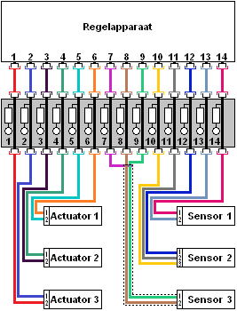
When voltages or signals need to be measured at the connector of the control unit, a breakout box can be placed between the wiring harness and the control unit (see the image below). The breakout box contains a large number of measuring points. Click here to go to the page about the breakout box.