Introduction:
With a duty-cycle circuit, the current through a consumer can be controlled. The current can be regulated without power loss occurring, as is the case with a series resistor. In automotive technology, the duty cycle can be used, among other things, to control the speed of the heater fan, the position of e.g. the throttle position motor, or the brightness of lighting.
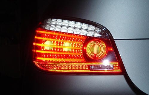
When applying a duty cycle to a lamp, it can be ensured that the lamp burns less brightly. This is used, among other things, for tail lights, where one bulb can burn at two different intensities, namely for normal lighting and for the brake light. With normal lighting, the lamp burns dimly (a duty cycle is applied here to limit the current through the lamp). When braking, the duty cycle of the lamp will change so that the lamp burns brighter.
The image shows a tail light of a BMW 5-series, where the left lamp of the tail light also functions as a brake light by making it burn more brightly.
Measuring a duty cycle:
A duty cycle can be measured with an oscilloscope. The oscilloscope will display the voltage variation with respect to time graphically.
When a duty cycle is measured with a multimeter, the correct voltage value will never be displayed. Because with a duty cycle the voltage is constantly varying, the multimeter will indicate the average voltage because it is too slow.

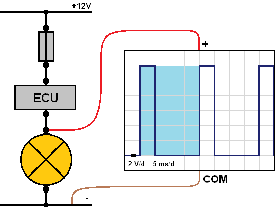
Duty cycle with positive-side switching:
In the image below, a waterfall diagram is shown with at the top the positive terminal of the battery (12 volts), followed by the fuse, the ECU (the electronic switch), the consumer (in this case a lamp) and finally ground. The ECU constantly switches the supply voltage on and off.
With the oscilloscope, the voltage is measured between the positive terminal of the lamp and the vehicle ground. The oscilloscope settings are as follows: 2 volts per division and 5 milliseconds per division. That means that each box from bottom to top represents 2 volts, so if the boxes of the rising line are counted (a total of 6), the highest measured voltage is 12 volts.
The time duration is from left to right. Each box (division) is set to 5 milliseconds. Looking from left to right, you can see that the line is high for 10 milliseconds and low for 10 milliseconds.
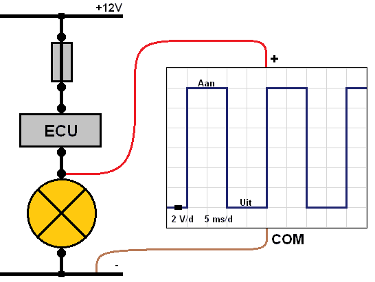
The oscilloscope, just like the multimeter, measures the voltage difference between the positive lead and the negative lead connected to the meter. In the diagram below, when the lamp is switched on, there is a voltage of 12 volts on the positive lead and (always) 0 volts on the negative lead because it is connected to ground. The difference between them is indicated by the meter; the difference between 12 volts and 0 volts is 12 volts. These 12 volts are displayed on the meter screen. When the duty cycle is high, the lamp is switched on. With ground-side switching, this is not the case. That is explained in the next paragraph.
To determine the duty cycle, it is important to know what one period consists of. In one period, the voltage is high once and low once. After this period, the next period begins. In the scope pattern below, one period is marked in blue. Here you can see that the period lasts a total of 20 milliseconds, namely 10 ms high and 10 ms low. It can therefore be read that half the time the voltage is high and the other half low. The duty cycle in this scope pattern is therefore 50%. In this case, the lamp burns dimly.
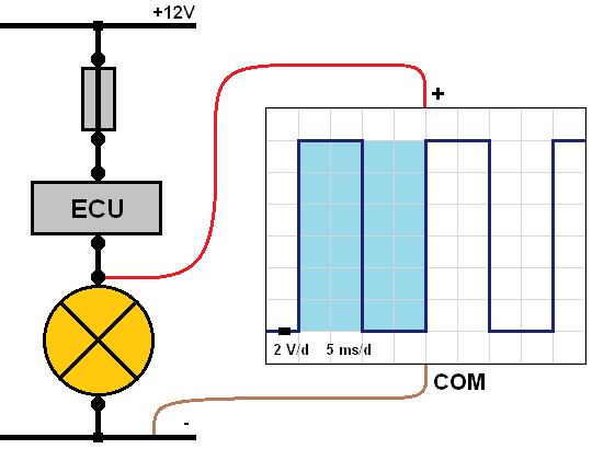
In the image below, the period has remained the same (20 ms), but in this case the voltage is high for only a quarter of the time (5 ms) and low for three-quarters of the time (15 ms). In this measurement, the duty cycle is 25%. That means that the lamp now burns even more dimly than with the 50% duty cycle, because the lamp only receives current for a quarter of the total period.
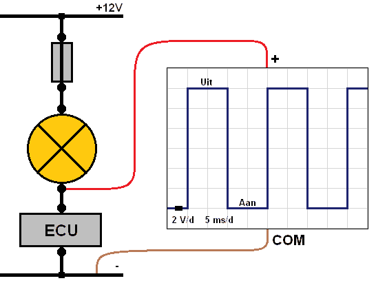
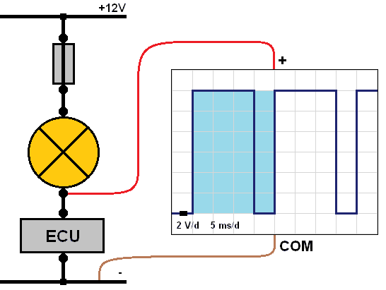
Duty cycle with ground-side switching:
In automotive technology, ground-side switching is usually used. With a ground-switched consumer, the duty cycle will be reversed compared to positive-side switching. An example of this can be seen in the image below.
When the lamp is switched off, the ECU has interrupted the connection to ground. That means the circuit is open. The 12-volt supply is then present at the ECU input. That means this voltage is also present at the lamp’s negative terminal. The voltage difference with a switched-off lamp is therefore 12 volts in this case.
As soon as the ECU connects the lamp to ground, the lamp will light up. A current then flows from positive to negative. The lamp uses the 12 volts to burn, so there is 0 volts at the lamp’s negative terminal. In that case there is 0 volts on the positive lead and 0 volts on the negative lead. The voltage difference is then 0 volts. That means that at 0 volts the lamp is switched on and at 12 volts the lamp is switched off.
In order to make the lamp burn more dimly, the time during which the lamp receives current must be shortened. This can be seen in the image below. In one period the voltage is high for 15 ms (lamp is switched off) and low for 5 ms (lamp is switched on). In this case, the lamp is switched on for only a quarter of the period, causing it to burn more dimly.
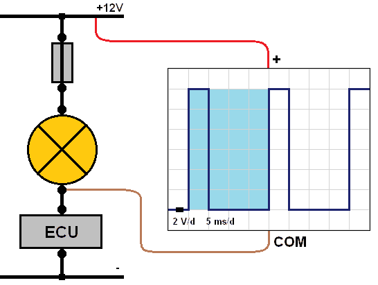
Duty cycle measured from the power supply:
The previous measurements were all taken with respect to the vehicle ground. Another possibility is to measure from the positive terminal of the battery to the ground connection of the consumer, as shown in the image below.
At the moment the ECU has connected ground, the lamp will light up. In that case, the 12-volt supply is used by the lamp in order to burn. There will therefore be a voltage of 0 volts on the oscilloscope’s negative lead. On the positive lead, there is a voltage of 12 volts. In that case, there is thus a voltage difference of 12 volts between the measuring leads, so the 12-volt level in the display will indicate that the lamp is switched on. This is therefore 25% of the period.
As soon as the ECU interrupts the connection to ground, the 12-volt voltage will also be present on the lamp’s negative side. The voltage difference between the oscilloscope measuring leads will then be 0 volts. At the moment the lamp is switched off, 0 volts are displayed.
Fault-finding in the PWM-controlled fuel pressure regulator:
On the page ECU circuit of a PWM valve it is explained what the circuit in the ECU of a PWM-controlled rail pressure regulator looks like. Therefore, it is recommended to first read the information on that page.
The rail pressure regulator on the high-pressure rail of the common-rail diesel engine is controlled by the engine control unit with PWM (Pulse Width Modulation).
At rest, the valve in the pressure regulator is open, allowing the fuel pressure to leave the high-pressure rail via the return. The valve closes at the moment it is actuated. The pressure in the rail increases. When the rail pressure sensor registers a (too) high pressure, the ECU adjusts the PWM signal.
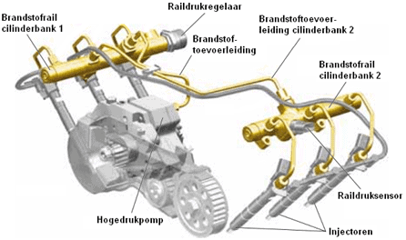
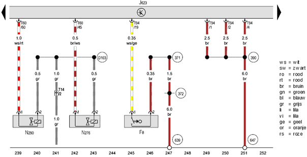
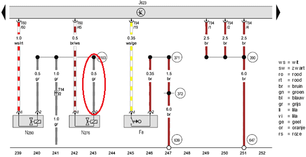
The image below shows the diagram of the engine control unit (J623) and the rail pressure regulator (N276). The rail pressure regulator is supplied at pin 2 with a voltage between 13 and 14.6 volts (depending on the charging voltage with the engine running). The ECU connects pin 45 to ground at the moment the valve needs to be actuated. A current will flow through the coil of N276 as soon as pin 45 is at ground. The pressure in the common rail increases. At the moment the ECU interrupts the connection between pin 45 and ground, the pressure build-up in the fuel rail stops. The spring in the pressure regulator opens the valve slightly again, allowing the fuel to flow back to the tank via the return lines.
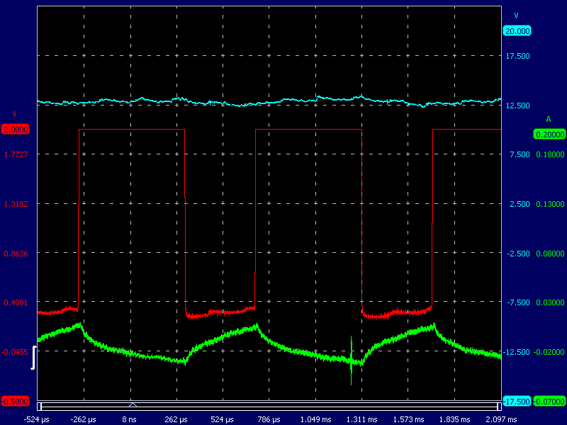
The scope pattern shows a supply voltage (blue) and the PWM control (red). The supply voltage is around 13.5 volts and is constant.
The voltage of the PWM control signal (red) is between 0 and 13.5 volts. In this scope pattern you can see that the valve is constantly being switched on and off.
The current (green) rises as soon as the valve is energized and drops after switching off.
At rest, the voltage is 13.5 volts. The PWM valve is not actuated.
The spring inside the valve ensures that the valve is open at rest.
At the moment the ECU switches ground on (in the scope pattern this can be seen at the moment the red signal is 0 volts) a current starts flowing through the coil (the green pattern), causing the valve to close.
In the scope pattern you can see that the valve is switched on for a short time and switched off for a longer time. That means that the fuel pressure must be relatively low.
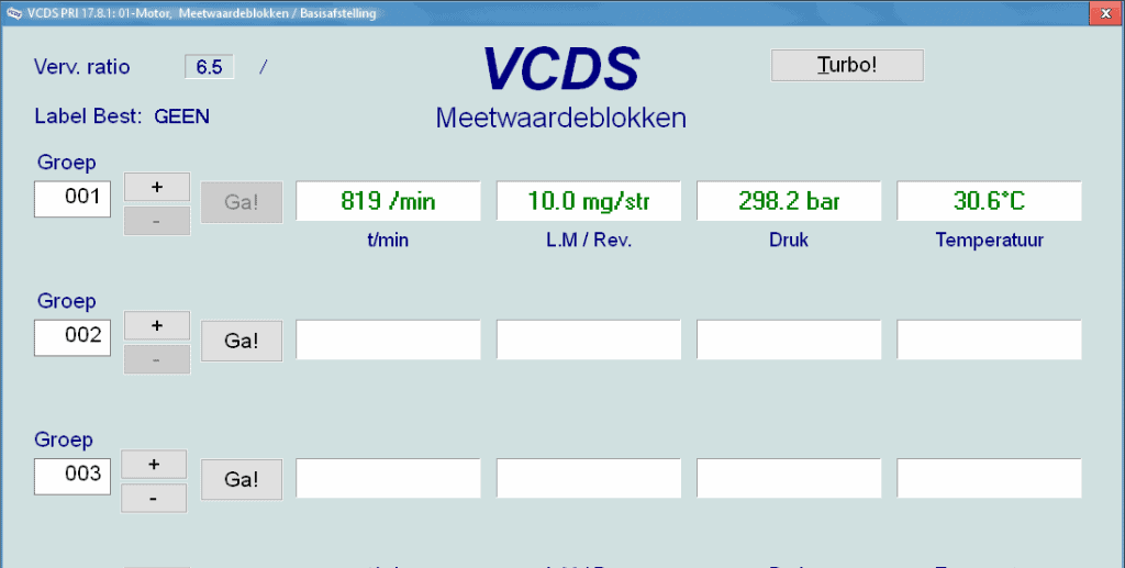
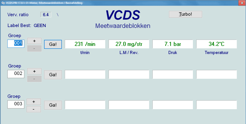
We read out the car and look at the live data. At idle speed, the fuel pressure is almost 300 bar. This is fine.
Fault: engine no longer starts while cranking.
While cranking, the engine does not start. We are certain that there is enough fuel in the tank. Of course, we start by reading out the fault codes. In this case, no fault codes are stored. Therefore, we look at the live data (in VCDS these are called measuring value blocks). While cranking, the cranking speed is 231 rpm. The ECU is receiving the crankshaft signal. That is good.
The fuel pressure during cranking is 7.1 bar. That is too low to start the engine.
Fuel pressure that is too low can have the following causes:
- too little fuel in the tank
- fuel pump (lift pump or high-pressure pump) defective
- clogged fuel filter
- defective fuel pressure regulating valve
In order to determine why the fuel pressure remains too low, we check the voltages of the electrical components with the oscilloscope.
Earlier in this paragraph, the scope pattern of the properly functioning PWM fuel pressure regulator was shown. The following scope pattern is again a measurement of this pressure regulator, but now with a fault.
During the increase of the current, the supply voltage decreases. The supply voltage therefore drops when current flows. In addition, the following points stand out:
- When switching on, the supply voltage drops to a lower value; normally, a contact resistance causes an abrupt drop (a vertical line in the scope pattern to a lower voltage);
- The current build-up after switching on the coil follows the characteristic charging curve according to the exponential function. The current behaviour during discharge is the mirror image of the gradual build-up of the supply voltage. The current does not drop to 0 A. So current continues to flow after actuation has ended.
- As soon as the coil is switched off, no induction peak can be seen in the red pattern (where the voltage rises from 0 to 14 volts). Think of switching off an injector coil where a peak of up to 60 volts can occur.
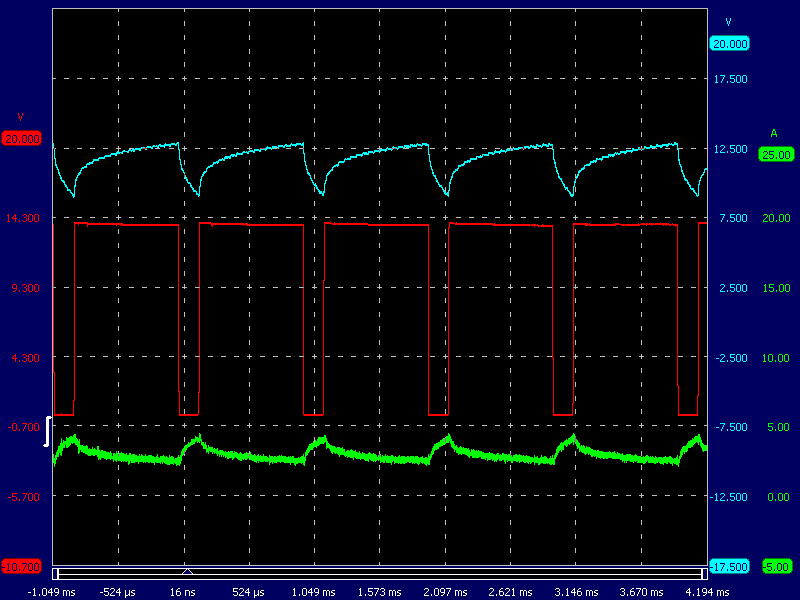
There is therefore a contact resistance in the supply wire to the fuel pressure regulator. Only when current flows does a voltage drop occur as a result of the contact resistance. With ground switched off, no current flows and the supply voltage remains neatly equal to the battery voltage.
Now back to the diagram: the supply wire is circled in red. The next step is to actually locate the damaged wire. Damage can occur as a result of chafing against engine components, or because the wire has been pinched during earlier assembly work. Once the damage has been found, it can be repaired.
It is now clear what the contact resistance caused. You may already have noticed that mention has been made of a missing induction peak in the scope signal. When the coil is switched off, the current pattern slowly drops to a lower value. There is therefore no interruption of the actuation; it is ended, but current still flows through the coil.
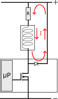
At the moment the FET is driven into conduction by the microprocessor, a current can flow from the drain to the source and thus through the coil. The coil is then energized and the control valve can close against the spring force thanks to the magnetic field created.
As soon as the actuation of the FET ends, no current flows via the coil to ground anymore. The freewheel diode ensures that the inductive current, as a result of the residual energy in the coil, is fed to the positive side. This results in a gradual decrease of the current and prevents an induction from taking place. This process is indicated by the red arrows in the image.
This explains why a current pattern is still visible in the scope even after actuation has already ended.