Trailer brake introduction:
The brake system of a truck with trailer has an extensive brake system to control the trailer’s brakes. The brake force is regulated via the trailer control valve (ECE valve). The lines of the trailer are connected to the tractor’s coupling heads with so‑called air couplings. The colours of these coupling heads indicate the different functions:
- Red coupling head: supply line. Through this line, the air compressor on the engine supplies air pressure to the reservoirs of the trailer.
- Yellow coupling head: control line. This transfers the brake command from the control valve on the tractor to the control valve on the trailer.
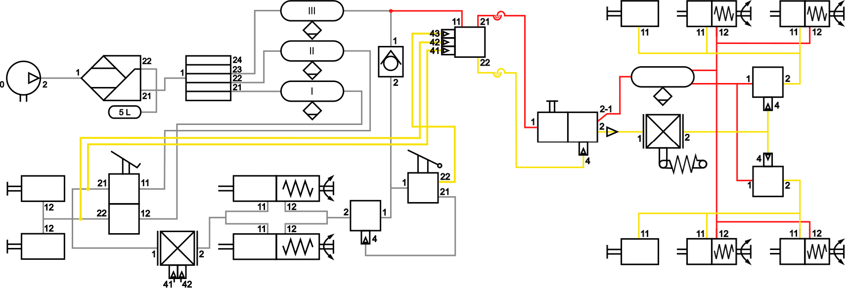
The image below shows the layout of the air brake system as depicted on the service brake and parking brake pages, with the trailer control valve (15) and coupling heads (16) added. On this page the air supply and air‑consuming part of the truck will not be discussed further, as it is assumed to be known.
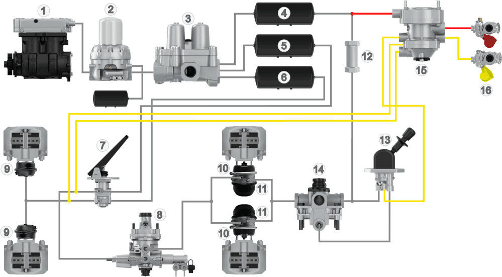
Legend:
1. Air compressor
2. Dryer with wet reservoir
3. Four‑circuit protection valve
4. Air reservoir circuit 3
5. Air reservoir circuit 1
6. Air reservoir circuit 2
7. Foot brake valve
8. Load‑sensing valve (ALR)
9. Diaphragm cylinders (front)
10. Diaphragm cylinders (rear)
11. Spring brake cylinders (rear)
12. Check valve
13. Parking brake valve
14. Relay valve
15. Trailer control valve
16. Coupling heads
- Red: supply
- Yellow: control
The diagram below also includes the trailer control valve and the coupling heads. Unlike the diagram on the “emergency and parking brake” page, the parking brake valve has an extra outlet: 22. This connection is linked to inlet 43 of the ECE valve.
The air reservoirs of the trailer are filled from air reservoir III and the red supply line (11 and 12 on the ECE valve). With the foot brake valve both the front and rear brakes of the truck are actuated, as well as the ECE valve at connections 41 and 42.
Connections 21 and 22 on the trailer control valve are connected to the red and yellow air coupling heads or a duo‑matic coupling. Using spiral air lines, the driver can connect the gladhands of the air hoses between the truck and the trailer.
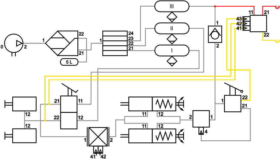
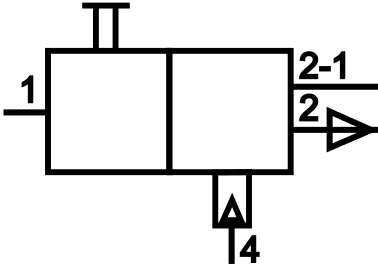
Markings on the ECE valve:
11: supply inlet
21: supply outlet
22: control outlet
41: circuit 1 inlet
42: circuit 2 inlet
43: circuit 3 inlet
- Red: supply
- Yellow: control
On the trailer side we also find air coupling heads to which the spiral air lines are connected. The yellow (control line) and red (supply line) both enter the trailer relay emergency valve (3). The supply air is passed directly on to the air reservoir (4). After sufficient pressure is reached, the relay valves (6) and spring brake boosters (8) are supplied with air. The parking brake is then released. See the “service brake” page for an explanation of the spring brake cylinders.
The mechanical ALR (5) is supplied with air from the control line. The brake pressure applied by the driver to the foot brake valve determines how high the control pressure at the ALR will be. The end of the lever on the ALR is connected to the chassis. The more the chassis is loaded, the further the air bellows or leaf springs are compressed. Based on this load, the mechanical ALR determines how much control pressure is passed on to the relay valves (6). A higher load means more brake pressure. Depending on the control pressure, the relay valves pass the supply pressure on to the diaphragm cylinders to press the brake linings against the discs or drums.
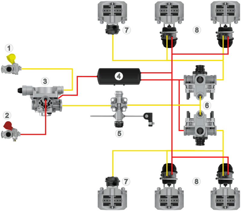
Legend:
1. Air coupling head control
2. Air coupling head supply
3. Trailer relay emergency valve
4. Air reservoir
5. Mechanical ALR
6. Relay valves
7. Diaphragm cylinder service brake
8. Diaphragm and spring brake cylinder service brake and parking brake
- Red: supply
- Yellow: control
The diagram below shows the symbols and markings of the components from the image above.
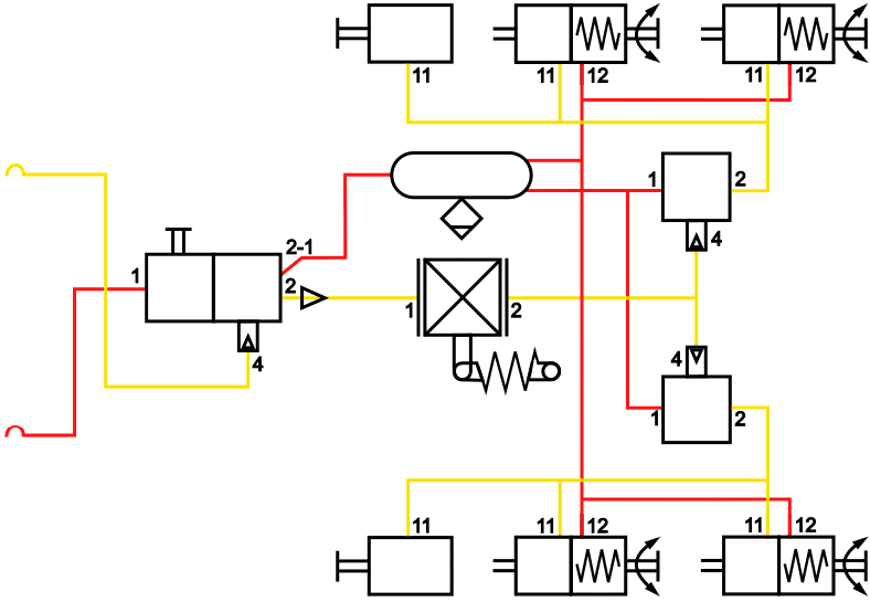
Legend for markings:
1. Inlet
11. Inlet 1
12. Inlet 2
2. Outlet
21. Outlet 1
22. Outlet 2
4. Control
In the diagram below, the diagrams of the truck and the trailer are shown connected together.
In the following paragraphs we will look in more detail at the operation of the components related to the trailer. To avoid duplication, the trailer components that correspond to those on the truck (such as the air reservoir, relay valve and brake cylinders) are not explained below. For these, see the pages: introduction, service brake and auxiliary & parking brake of the truck.
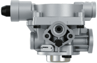
Trailer control valve (ECE valve):
The trailer control valve is also called an ECE valve or ECE valve body. This valve is located on the truck and regulates the brake pressure to the trailer when the service brake or the emergency and parking brake is operated. There is an adjustment screw on the trailer control valve to set the trailer’s lead braking. More about this in a separate paragraph.
The images alongside show the trailer control valve and its symbol. The red lines (11 and 12) are the inlet and outlet of the supply pressure, and the yellow ones (22, 41, 42, 43) are for the control pressure.
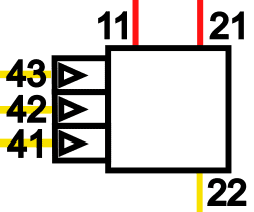
The trailer control valve receives the brake pressure from an air reservoir at connection 11. Connection 21 sends the supply pressure to the trailer via the red hose. Connections 41, 42 and 43 come from the foot brake valve and the hand brake valve. The pressure in these lines determines how high the control pressure (22) sent out will be, which actuates the trailer’s brakes.
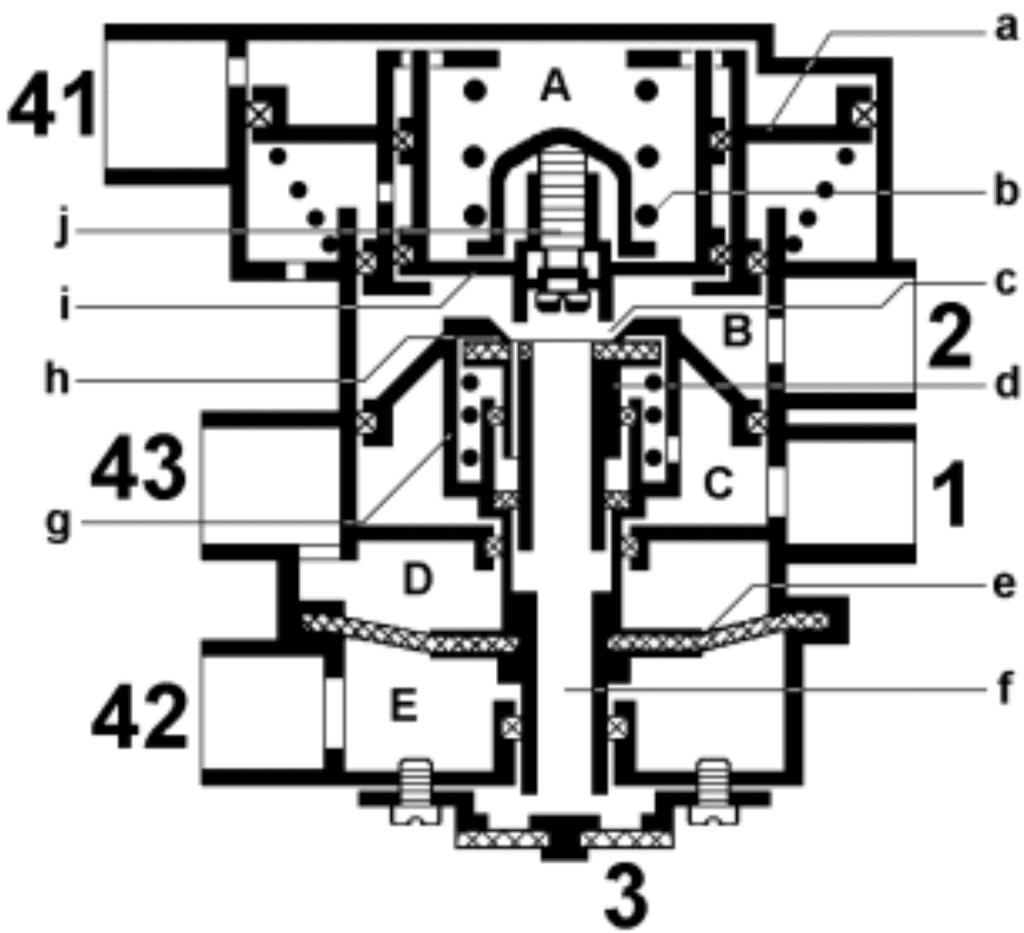
Brake not applied:
The supply pressure of circuit 3 enters at connection 1. Chamber B is not pressurised because ports b and h remain closed.
Partial braking:
When the driver brakes, the brake pressure from the foot brake valve enters at connections 41 and 42. The air pressure from connection 41 pushes piston f downwards and eventually opens seat b. The air from chamber C flows to B and leaves via connection 2 of the control valve towards the yellow control line. Due to the pressure in chamber B, the pressure on the underside of piston f increases and closes the standpipe. There is now an equilibrium situation for partial braking.
Hard braking:
During hard (full) braking, the pressure on piston f will be at maximum. The standpipe is fully pressed shut and lifted maximally from its seat. There is therefore no longer an equilibrium situation. Connection 2 remains pressurised to the maximum, so the control pressure is also at maximum.
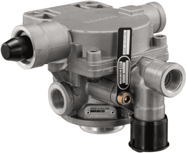
Trailer relay emergency valve:
The trailer relay emergency valve is located on the trailer and has two functions:
- The valve operates the trailer’s brake system when the truck’s brakes are activated. The brake pressure depends on the pressure sent out by the trailer control valve.
- The valve also operates the trailer’s brake system when the pressure in the supply line suddenly drops sharply due to a leak in a circuit.
Filling the system:
When coupling and connecting the trailer, air is supplied from the truck to connection 1. When the trailer’s air system is still without pressure, the air flows both to connections 2‑1 (to the reservoir) and 2 (to the ALR). Because there is also pressure at connection 2, the service brake of the trailer is actuated at the same time. The service brake remains applied until a reservoir pressure of 3 bar is reached. At that point, the internal connection between connections 1 (inlet) and 2 (ALR and diaphragm cylinders) is closed. The service brake is then released. Filling the air reservoir continues until a pressure of 8 bar is reached.
Braking:
During partial braking, the control pressure (command pressure) from the trailer control valve on the truck flows via the control line to connection 4 of the trailer relay emergency valve. The trailer relay emergency valve then lets air through from connection 1 to connection 2, causing the trailer to brake, depending on the axle load measured by the ALR. The control pressure at connection 4 determines how hard the trailer will brake. In vehicles with EBS, the control pressure at connection 4 is blocked by a solenoid, and the control pressure is measured by a pressure sensor. The level of this pressure is sent to the EBS control unit (trailer modulator) for further processing.
Hose rupture protection and break‑away braking device:
The trailer relay emergency valve contains a hose‑rupture protection device that ensures that the trailer brakes fully when it becomes detached from the truck. When the supply line is disconnected or breaks, the ALR causes the relay valves to open fully so that the reservoir pressure flows to the brake cylinders. To release the brakes again, they can be released via the release valve on the trailer relay emergency valve.
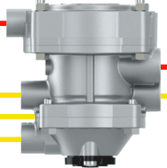
The images below show a trailer relay emergency valve with an associated Wabco diagram.
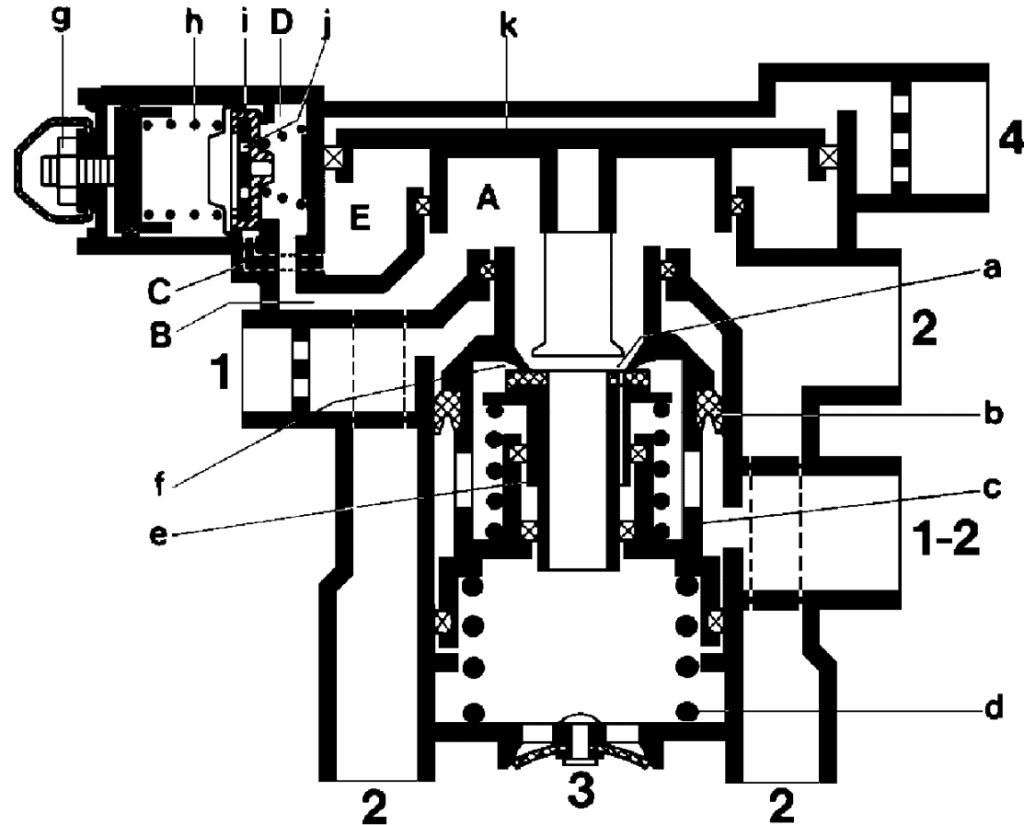
Pre-control:
With a truck and trailer combination, it is important that they both brake equally hard. When either the truck or the trailer brakes too hard, this can create dangerous situations (think of jackknifing of the combination) or cause extra wear on the brake components or the couplings, such as the fifth wheel or kingpin of a semi-trailer, or the drawbar and drawbar eye of a steered trailer. With pre-control, the braking deceleration of the truck and trailer can be matched. When both the truck and trailer brake equally hard, we call this a “harmonization”.
The pre-control can be set on the trailer control valve by slightly increasing the delivered control pressure. The pressure flows more quickly through the line and thus compensates for the flow losses in the control line and hoses between the trailer control valve on the truck and the brake cylinders of the trailer.
The pre-control can be adjusted by turning bolt j (see the illustration alongside). This changes the preload of tension spring b. By adjusting this spring tension, the pressure required to move piston a against the control pressure of port 41 is changed. The pressure increase is steplessly adjustable between 0.2 and 1.0 bar of pre-control.
By measuring the pressures, the pre-control can be adjusted. It is not intended that this screw be turned without taking measurements, because this will affect the brake balance between truck and trailer.
The pre-control of the trailer control and reaction valve can be determined by measuring the input and output pressures with pressure gauges. Consult the workshop documentation for the specified pressures.
We want to measure the pressure at port 41 of the trailer control valve. Because there is no test point here, another point must be located in the diagram. This is at inlet (1) of the pneumatic ALR of the truck. Pressure gauge 1 is connected here to read pressure p1.
We connect pressure gauge 2 to the control line after the trailer reaction valve. The pressure difference between p1 and p2 is the pre-control of the towing vehicle. For a good overview, pressure gauge p3 can be connected to inlet 1 of the ALR on the trailer, but this is not necessary for measuring the pre-control.
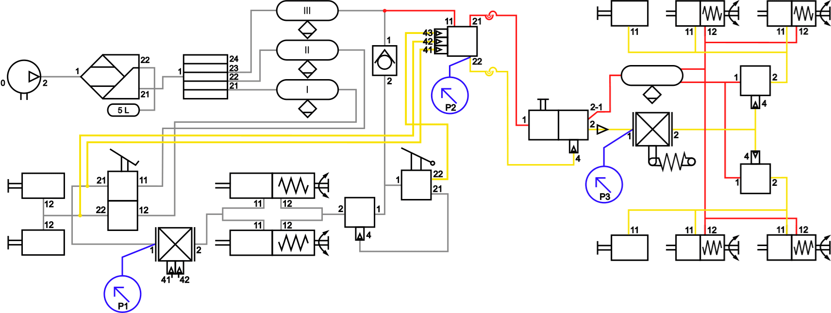
Example of measurement results of the pre-control:
- input pressure p1: 2.0 bar
- output pressure p2: 2.5 bar
- pre-control: 2.5 – 2.0 bar = 0.5 bar
If the manufacturer specifies that the pre-control must be 0.3 bar, the adjustment screw on the ECE valve can be turned so that at the next measurement the output pressure will be 2.2 bar, making the pre-control (2.5 – 2.2) = 0.3 bar.
Related page: