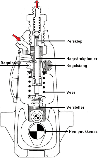
High-pressure in-line pump (PE):
The high-pressure in-line pump represents the first generation of diesel fuel pumps. A high-pressure in-line pump consists of as many plunger elements as there are cylinders. Each plunger supplies the fuel for its own cylinder. The high-pressure plungers are operated by the internal pump camshaft. When these plungers are pushed upwards, they create the delivery stroke (which forces diesel through the line to the cylinder). The high-pressure in-line pump works with a fixed stroke. The fuel delivery is controlled by rotating the plungers. This rotation is carried out by the control rod, which is indirectly connected to the accelerator pedal. When the accelerator pedal is pressed, the plungers are rotated, thereby regulating the fuel output.
The governor is also located in the pump (visible in the images below), which, among other things, ensures that the diesel engine idles at the most stable speed possible and adjusts the fuel output as the speed increases.
An in-line pump suffers from internal leakage losses. These leakage losses arise mainly due to imperfections in the sealing of the cylinder: the cylinder wall may be microscopically uneven, leaving room for leakage along the piston. At lower speeds and low pressure levels, small amounts of diesel fuel may leak past the seals of the plungers or other internal components. This can occur because the seals do not close perfectly or due to wear over time.
As the pump speed increases, the pressure inside the pump usually rises. This higher pressure can help reduce the imperfections in the seals and components, thereby reducing the leakage losses. This is because the higher pressure presses the seals against the moving parts and reduces the likelihood of leakage.
When the fuel supply is not properly regulated, causing too much fuel to be injected into the engine, this can lead to an excessively high governed speed.
- If there is a fault in the fuel control of the in-line pump, the plungers may inject more fuel than is necessary for the current speed. This can lead to an excessive combustion rate and an engine speed higher than recommended;
- If the control rod that is responsible for adjusting the fuel delivery fails, the in-line pump may not respond correctly to the accelerator pedal. This can result in an unintended increase in fuel supply and thus in engine speed;
- Physical faults in the in-line pump, such as sticking plungers, damaged components or mechanical blockages, can disrupt the normal regulation of the fuel supply and possibly lead to an uncontrolled higher engine speed.
Rotary distributor pump (VE):
As the successor to the high-pressure in-line pump, the rotary distributor pump (the CAV DPA and the Bosch VE) was developed. This fuel pump operates entirely mechanically. The advantages of the rotary distributor pump compared to the in-line pump are the smaller number of plungers (and thus the installation size) and the standard injection timing adjustment.
Bosch VE pump:
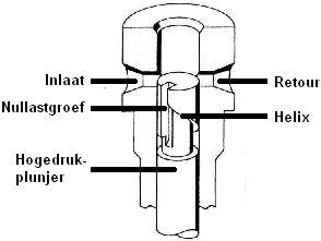
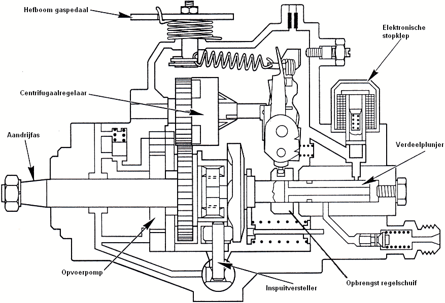
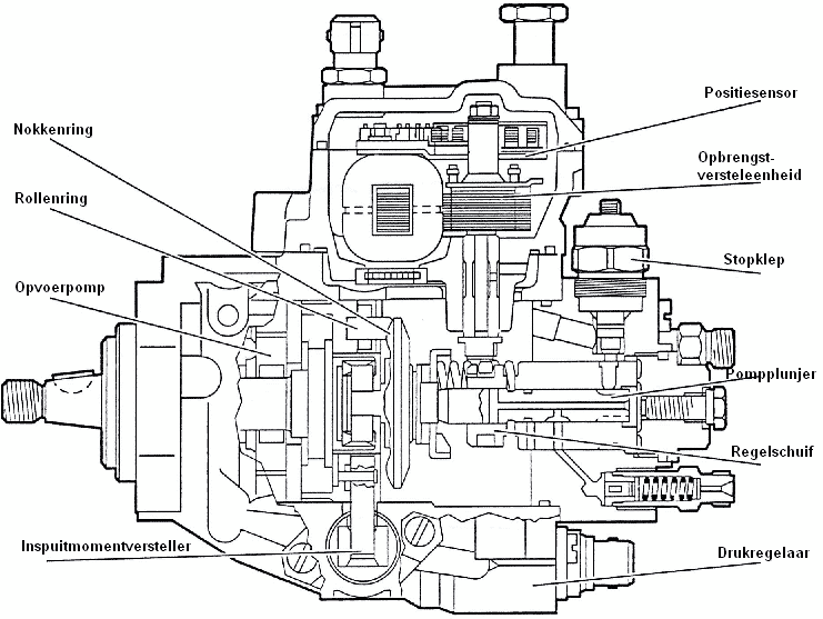
The Bosch rotary distributor pump is a fully mechanical pump. The lever on the pump is directly connected to the accelerator pedal. The pump operates with a plunger that moves axially. The plunger makes both a rotating and a reciprocating movement (this is explained in detail below). The control sleeve (connected to the accelerator pedal) and the centrifugal governor ensure the correct fuel metering. When the control sleeve moves to the left, fuel can leave the pump through the return opening, thereby reducing the amount of fuel. As soon as more fuel is required (higher speed or load), the control sleeve moves further to the right, increasing the fuel volume to the injectors. With a constant engine load, the engine speed will then increase.
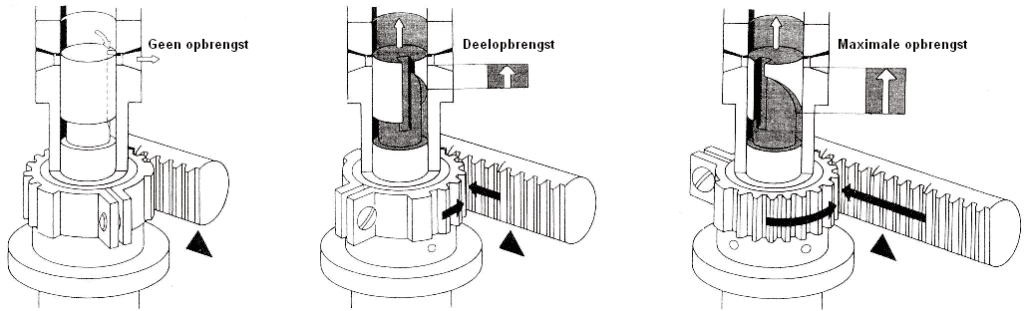
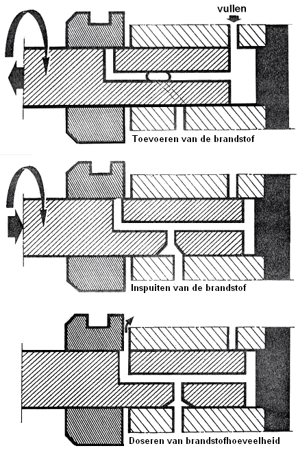
The plunger in the Bosch VE rotary pump is responsible for supplying, injecting and distributing the fuel. These three steps are explained below with the help of three illustrations.
1. Supplying the fuel:
The plunger is rotated to the left, allowing the fuel – coming from the feed pump – to flow via the inlet channel above the plunger to the delivery chamber to the right of the plunger.
2. Injecting the fuel:
The cam plate pushes the plunger to the right. This closes the inlet channel to the delivery chamber and the volume in the delivery chamber becomes smaller. The pressure on the fuel increases until, by rotation, a connection is made with the outlet channel. Every 90 degrees there is an outlet, to which the pressurised fuel flows.
3. Metering the fuel quantity:
The position of the control sleeve determines the end of injection, and therefore how much fuel is delivered via the outlet to the injector.
The position of the control sleeve is determined by the centrifugal governor. This component is described below.
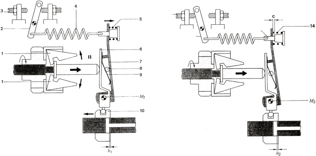
Centrifugal governor:
The accelerator pedal is indirectly connected via spring 4 and the lever system (6, 7, 8, 9) to control sleeve 10. In the position shown (left), the accelerator pedal is fully depressed and the control sleeve will tend to move to the right for maximum output. M2 is the pivot point. When the governed speed is reached, the centrifugal force will tend to move the governor sleeve II to the right, causing control sleeve 10 to move to the left. An equilibrium is therefore created between spring 4 and the centrifugal force. The speed is controlled by the output regulation.
In the right-hand image, the regulation at idle speed is shown. The accelerator pedal is not depressed and the lever is completely in the right-hand position. A weak spring (14) now ensures the equilibrium.
Injection advance:
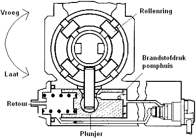
Rotary fuel pumps are always equipped as standard with injection advance. When the speed increases, injection has to take place earlier in order to achieve an effective power stroke. Otherwise, at higher speeds, the diesel mist injected by the injector will not have enough time to mix properly with the air. As engine speed rises, the injector therefore has to inject a few degrees earlier before TDC (Top Dead Centre). The injection advance system consists of a plunger that is connected to a roller ring. As speed rises, this roller ring is rotated in the direction of rotation, so that the injection plunger starts the pump stroke (and thus the injection) earlier. No electronics are used for this injection advance.
Adjusting the rotary distributor pump:
It is important that the pressure build-up in the pump takes place at the correct moment. The pressure build-up determines the injection timing of the diesel fuel by the injectors. The position of the fuel pump can be changed relative to the engine block. There are slotted holes in the engine block in which the fuel pump can be moved. Rotating the pump has no effect on the gear driven by the timing belt. The gear remains stationary, but the pump behind it is moved to a different position. For a timing drive that rotates clockwise, the following applies:
- Moving the pump counterclockwise results in earlier injection;
- Moving the pump clockwise results in later injection;
The fuel pump must therefore be adjusted on the basis of the crankshaft position and the position of the control sleeve. This must be carried out using a dial gauge.
Below is a step-by-step plan showing how to adjust a rotary distributor pump.
1. Place the piston of cylinder 1 at TDC.
Rotate the crankshaft until the piston of cylinder 1 is at top dead centre.
You can see whether the crankshaft timing is correct by checking whether the timing mark on the flywheel lines up with the mark in the gearbox housing.
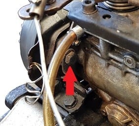
2. Timing of the fuel pump
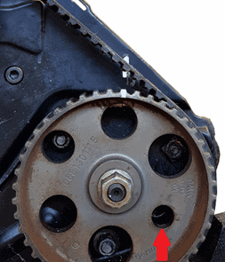
Check whether the timing of the fuel pump is correct. The two timing marks (highlighted in white in the image) must be opposite each other. If the fuel pump timing is not correct, the timing belt must be removed and refitted correctly.
Then insert the locking pin (in the image, in the hole with the red arrow).
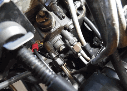
3. Removing components
Remove the fuel lines, the coolant hose and the thermostat housing to create space behind the fuel pump. You need this space to be able to install the dial gauge in the pump.
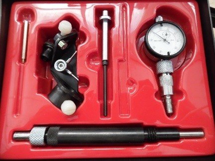
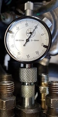
4. Dial gauge
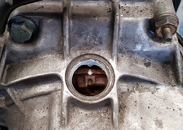
Find the dial gauge with which the fuel pump must be adjusted.
Screw the loose parts of the dial gauge together. Remove the blanking plug from the fuel pump and screw in the dial gauge. Make things easy for yourself by positioning the dial gauge so that it is clearly visible while the crankshaft is being rotated.
4. Set a preload.
Because you want the needle of the dial gauge always to touch the inside of the pump, you set a preload. This pushes the dial gauge a little further into the pump housing.
Set this preload to at least 2 millimetres (see image).
5. Rotate the crankshaft in the normal direction of rotation.
The crankshaft must be rotated. The needle of the dial gauge will move as you do this. Because the distributor plunger makes a reciprocating motion, the needle will at some point remain stationary. When the crankshaft is rotated further, the needle will move back again.
At the point where the needle remains stationary, the maximum stroke of the distributor plunger has been reached.
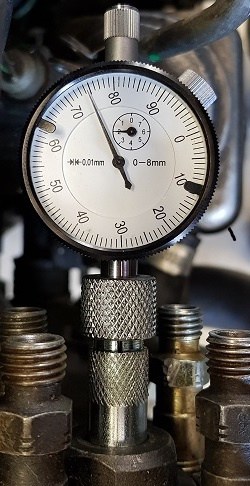
6. Set the dial gauge to 0.
Rotate the black ring on the dial gauge and set it to 0.
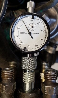
7. Place the piston of cylinder 1 at TDC.
Rotate the crankshaft again until the piston of cylinder 1 is at TDC. Check the timing marks on the flywheel and the gearbox housing again.
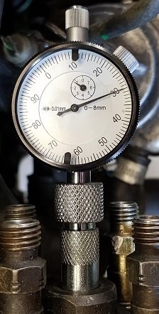
Read the value on the dial gauge indicated by the needle. The needle has moved counterclockwise. This means that the distributor plunger has made a stroke of
0.70 mm. Compare this value with the factory specifications. When the values correspond, no adjustment is necessary. If the value is incorrect, the pump must be adjusted.
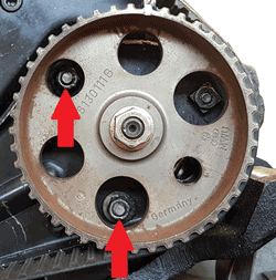
8. Adjusting the fuel pump.
Adjust the fuel pump by loosening the three bolts (shown in the illustrations) one turn and shifting the position of the pump on the engine block.
Electronically controlled distributor pumps:
Nowadays, diesel engines, like petrol engines, are controlled by an ECU (an engine control unit). With the help of this computer, various functions of the high-pressure fuel pump can also be controlled and the fuel metering can be adjusted much more precisely than with a fully mechanical fuel pump. The electronically controlled distributor pumps are divided into the following three types:
- Lucas EPIC pump
- Bosch VP-/ VR-pump
- Bosch VP44
Lucas EPIC pump:
The Lucas EPIC pump is a fully electronically controlled rotary fuel pump. The following functions are controlled: start quantity, idle speed control, part-load quantity control, full-load control, injection timing control, self-diagnosis.
Bosch VP pump:
The VP pump from Bosch is internally identical to the mechanical VE pump described earlier on this page. Components such as the feed pump, the cam ring, the control sleeve, the pump distributor housing and the pump plunger are unchanged.
Compared to the VR pump, the VP pump has the following new components:
- Control unit (actuator) to control the position of the control sleeve.
- Sensor to determine the position of the control sleeve.
- Injection timing adjuster; this is actuated via a PWM signal (PWM stands for Pulse-Width Modulation). The PWM signal comes from the ECU.
The control unit adjusts the position of the control sleeve. This is done by using a permanent magnet and an electromagnet that is actuated with a duty cycle. When the electromagnet is supplied with voltage by the ECU, it becomes magnetic and will be attracted towards the permanent magnet. The longer the duty-cycle signal, the more magnetism is generated and thus the greater the movement (adjustment) it makes. When the duty-cycle signal disappears, the spring will pull the adjuster back.
The position sensor is an inductive sensor which monitors the rotation of the shaft of the aforementioned control sleeve. In this way the ECU has feedback that the desired positions have in fact been reached.
Injection advance:
The injection advance system is similar to that of the Bosch VE pump. Only with this VP pump, the advance is controlled by a PWM signal from the ECU. In short, the ECU determines the position of the cam ring and not the engine speed, as was the case with the VE pump.
The position of the cam ring controls the injection timing. The position of the plunger determines the rotation of the cam ring. The plunger is pushed to the left, against the spring force, by a fuel pressure that the pressure regulator in the pump housing allows.
The fuel flows under pressure through the fuel pressure regulator to the return line. As soon as the ECU sends a signal, this regulator ensures that the internal supply is opened slightly more or less. When the supply is opened, fuel pressure flows into the pump housing, causing the entire plunger to be moved to the left against the spring force. This causes the cam ring to be rotated to the right (clockwise). That means that the cam ring is rotated in the “early” direction. Injection now takes place earlier before TDC. As soon as the fuel pressure in the pump housing drops, the spring ensures that the plunger returns to its initial position. The cam ring therefore moves back to “late”.
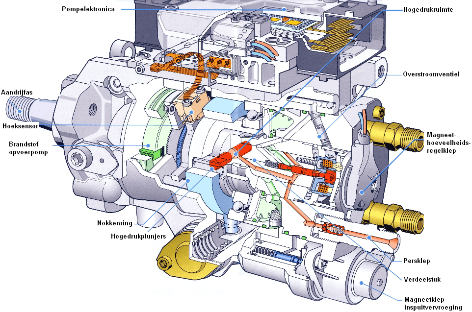
Bosch VP44 pump:
In the radial VP44 pump, unlike in the VE and VP pumps, the pump plungers are not positioned in the longitudinal direction of the shaft but transverse to the drive shaft. This high-pressure pump also draws in the fuel itself and controls the injection advance itself. The maximum injection pressure is up to 1850 bar.
When the pump is running, the plungers are pushed inward by the cams on the cam ring. When the solenoid valve is closed, pressure can be built up and, by the rotation of the distributor shaft, a connection is made with one of the injectors. At that moment the injection takes place.
Malfunctions due to prolonged standstill:
Prolonged standstill of the engine can in some cases lead to problems with the fuel pump and the fuel system. Here are some possible scenarios in which prolonged standstill can have an impact:
- Fuel degradation: If the fuel remains stationary for a long time, it can degrade and cause condensation. This can lead to the formation of sediments and impurities in the fuel that can eventually clog the fuel pump and injectors;
- Evaporation and varnish formation: If fuel in the fuel lines evaporates, resin-like deposits can remain that can hinder the free flow of fuel;
- Seals and rubber components: Prolonged standstill can lead to drying out and hardening of seals, gaskets and rubber components in the fuel system. This can cause leaks or compromise the sealing of the system;
- Sticking moving parts: As a result of oxidation and contamination, it can happen that moving parts in the fuel pump seize. This can prevent the pump from building up the required fuel pressure.
To prevent these kinds of problems during prolonged standstill, it is advisable to take precautionary measures, such as using fuel additives, not leaving the car with a low fuel level to prevent condensation from forming in the tank, and running the engine regularly to ensure everything remains lubricated.