Ignition switch:
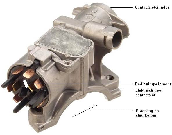
The picture below shows the rear side of an ignition switch. The ignition lock cylinder is located at the front and, together with the operating element at the back of the cylinder, moves the electrical part of the ignition switch.
Because the electrical part (also called the contact block) moves relative to the housing, various switching configurations are possible. The key position indicates which contacts in the electrical part are connected to each other (for example, when the constant positive wire (terminal 30) is connected to the positive wire of the starter motor (terminal 50b), the engine is cranked. When the key is released, terminal 15 (ignition/“contact”) remains switched on. When the key is fully turned to the left again (in the off position), all contacts are broken and the engine and ignition are switched off).
When the key is removed from the ignition and the steering wheel is turned, the steering lock is activated. A metal pin moves from the ignition switch into a recess in the steering column. To unlock the steering lock again, the ignition key must be turned in the ignition switch while a slight steering movement is made.
The operation of the lock cylinder is described on the lock cylinder page.
Nowadays, ignition switches without a lock cylinder are increasingly being used; they work fully electronically by means of a plastic chip or key.
Electrical part of the ignition switch:
Behind the lock cylinder is the electrical part, also called the “contact block”. Its purpose is essentially to convert the movement made with the key into voltages on the correct wires; in other words, selecting the accessory position and starting.
The electrical part is often locked in place with a small screw and is therefore relatively easy to remove from the housing of the ignition switch when a repair is needed.
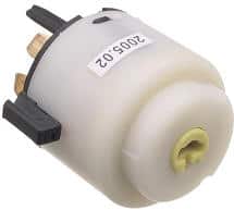
In the image on the right you can see the front side of the contact block. In the middle there is a yellow, round, rotatable part with a horizontal slot. When the key is inserted into the ignition switch, the end of the key will slide into this slot. When the correct key is inserted into the cylinder lock, it can rotate thanks to the wafers in the ignition switch. What you are actually doing is rotating the yellow part in the contact block. Internally, the switching contacts (onto which the connector is plugged at the rear) are connected to each other. This is explained in more detail in the diagram in the next paragraph.
It may happen that the car can no longer be started. In that case, the contact block may be defective internally. To check this, the control voltage on the small wire to the starter motor can be measured.
On older cars it was sometimes possible to unplug the connector from the contact block and then bridge certain contacts with your own wire. Or to rotate the yellow part with a screwdriver as you can see in the image above. This way the car could be started and driven. Car theft often happened this way.
To prevent this, every modern car is now equipped with an immobiliser. The key number of the transponder in the key is compared with the stored values. If they do not match, the engine will stall again immediately after starting. It is therefore no longer possible to start and keep the engine running merely by bridging wires or just operating the contact block.
Diagram of ignition switch with load reduction relay:
The diagram below shows the ignition switch. In it you can see the component codes such as CS for the ignition switch and RX for the load reduction relay. The terminal designations 15, 30, 31, 50 and 75 are also shown here.
When the ignition switch is turned to position 1, terminal 15 is connected to terminal 30. This switches the ignition on and supplies power to consumers in, among other things, the interior. During starting, terminal 50(b) is supplied with voltage, causing the starter motor to turn. When the ignition switch is turned to position 0 but the key has not yet been removed from the lock cylinder, there will still be voltage on terminal 75. Consumers such as the radio are connected to terminal 75. On the car in this diagram, the radio will therefore remain on when the ignition is switched off and the key has not yet been removed from the lock cylinder.
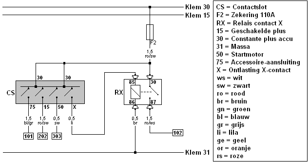
The function of the load reduction relay contact X (in English called the “load reduction relay”) is to switch off consumers that require a lot of voltage and current to operate, such as the blower (interior fan), the radio, the dipped beam headlights, the rear window defogger, the seat heating etc., at the moment the engine is started. During starting, switch X in the ignition switch opens (as is currently shown in the diagram). The voltage to the electromagnet (between terminals 85 and 86 of the relay’s control side) is interrupted. As a result, no main current will flow from terminal 30 to 87, causing the consumers, which in another diagram are connected to wire number 102, to be temporarily switched off. At that moment, more current is available for the starter motor than when other consumers are drawing a lot of current. That is why this component is called a load reduction relay.
When the ignition key is turned back again after the engine has started, switch X in the ignition switch will close again. Relay RX will be energised again, so that the consumers are once more supplied with voltage and current.