Introduction to LIN bus:
The LIN bus (short for Local Interconnect Network) does not work with two wires like the CAN bus, but with a single wire between two or more control units. With the LIN bus there is a master and a slave; the master sends a message and the slave receives it. The master is connected to one of the other networks, such as the MOST bus or the CAN bus.
The master can be a control unit or a simple switch, and the slave can be a sensor, actuator or a control unit. This could be, for example, for controlling an air conditioning compressor or operating a window motor. In that case the switch is the master and the window motor is the slave.
Some applications in which LIN bus is used for control include:
- Sliding / tilting roof
- Mirror adjustment
- Window motors
- Door locks
- Electric seat adjustment
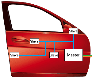
In the image on the right you can see how the LIN bus can be used in a door. The master is connected to the gateway via the CAN bus (orange and green wires). Four slaves are connected to the master; the top one for mirror adjustment, below that for the door handle electronics, and below that to the left for the lock and to the right for the window motor.
Compared to the CAN bus, the LIN bus is simple and slow. The speed of the LIN bus is about 1 up to a maximum of 20 Kbit/s (compared to the CAN bus with a maximum speed of 20 Mb/s). This makes development and production of the components much cheaper. Because, for the above-mentioned systems, it is not important that they are controlled via a very fast network like the CAN bus, a slow network such as the LIN bus is sufficient. Furthermore, the maximum cable length is 40 metres and a maximum of 16 control units (so up to 16 slaves) can be connected.
The LIN bus is connected to the gateway. Via the gateway, communication with other types of networks such as the CAN or MOST bus is possible.
Recessive and dominant:
The master sends a message to the slave. This information is transmitted using voltages of either 0 volts or 12 volts. The LIN bus signal can be measured with the oscilloscope.
At point 1 there is a voltage of 13 volts on the bus. At point 2 the master starts sending a message. The master switches the bus to ground (point 3). Within 0.1 milliseconds the line rises back to 13 volts. During the time the bus is switched to ground, information transfer takes place.
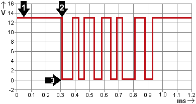
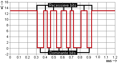
When the voltage on the bus is equal to the battery voltage, this is called recessive. During the recessive voltage no information is transmitted.
The recessive bit is a logical 1.
Only when the bus is switched to ground is a logical 0 formed. This is called a dominant bit. In the signal the bus becomes dominant several times and then recessive again. The time that the bus is dominant or recessive also differs (one horizontal line is wider than the other). Due to this varying voltage, a signal consisting of ones and zeros is formed.
The number of ones and zeros forms a signal that is recognised by the slave. The combination 01101100010100 can mean: window motor up. The corresponding window motor will move the window up with this command. When the window has reached its highest position, the window motor (the slave) will send a signal to the master that it should stop driving. In that case, the LIN bus does not become fully recessive, but the data bytes in the signal change.
The LIN bus never becomes fully recessive while the car is in use; there is always communication taking place between the master and the slaves. When the slave does not communicate because the LIN bus wire is interrupted, or when the slave has a power supply or ground problem and cannot be switched on, the master will ensure that a fault code is stored in the control unit.
Data frames:
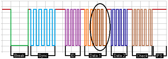
A LIN bus signal consists of a frame that is built up from different fields. The signal below shows how a data frame is constructed.
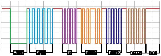
- Break field (Break): the Break field is used to activate all connected slaves so that they listen to the following parts of the frame. The Break field consists of a start bit and at least 13 dominant bits (in the dominant part the voltage is 0 volts), followed by a recessive bit. The Break field therefore serves as a start-of-frame notification for all slaves on the bus.
- Synchronisation field (Sync): due to the lack of crystals in the slaves, the transmission time has to be determined again for each message. By measuring the time between the defined rising and falling edges, the master clock is synchronised and the transmission speed is determined. LIN slaves are intentionally designed to be simple and inexpensive. That is why they do not have their own crystal oscillator for a fixed and accurate clock. The baud rate of the slave is therefore not fixed and must be determined again with each LIN message.
- Identifier (ID): the identifier indicates whether the message is a transmit frame or a response frame. The transmit frame is sent by the master (this is called a TX-ID) and the response frame is sent by the slave (RX-ID). Both messages contain the break field, the sync and the message ID fields that are generated by the master. Depending on whether it is a Tx or an Rx frame, the message is supplemented by the master or the slave. The Tx and Rx frames are sent alternately. This allows the master to request information from the slave. The master sends the first part of the message up to the ID field, the slave completes it with all data blocks up to and including the checksum.
- Data fields (Data 1 & 2): contain the data bytes and contain the information that must be sent (for example the actual command from the master to the slave, or sensor information from the slave to the master).
- Checksum (Check): The checksum is a control field where it is checked whether all data has been received. A calculation is performed with the data in the checksum field which must correspond to the data that has been received in the data fields. If the result is positive, the message is accepted. If the result is negative, an error handling is carried out. First it is retried.
- Interframe Space (IFS): the LIN bus is made recessive for a number of bits before a new message is sent. After the IFS, the master can send a new message.
Between the different fields, the bus is recessive for a certain time. This time is defined in the protocol. Then the Break field of the next message follows. The oscilloscope image below shows a LIN bus message from a wiper motor.
LIN bus communication of the seat heating button:
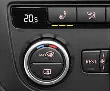
This paragraph provides an example of controlling the seat heating via LIN bus. There is a button for the seat heating in the air conditioning control panel. Under the button there are three LEDs that indicate the position of the seat heating. Pressing the button several times will change the seat heating setting (position 1 is the lowest and position 3 is the highest setting). In the image below, three LEDs are lit as an indication of the highest seat heating setting. In this paragraph, a diagram is used to explain how communication via the LIN bus is used to control the LEDs when the switch is operated.
The wiring diagram below is of the seat heating. The air conditioning control panel is also the control unit G600. In the control panel, the switches and LEDs of the left and right seat heating are visible. The arrows next to the control units indicate that the control unit is larger than shown in the diagram; the control unit continues in other diagrams.
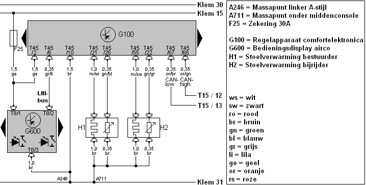
When a seat heating button on the control panel is pressed, it sends a signal via the LIN bus to the comfort electronics control unit (G100).
Control unit G100 will switch on the seat heating by supplying voltage to pin 21 or 55 on connector T45. The voltage is adjusted according to the position of the switch (low voltage in position 1, maximum voltage in position 3). Next to the heating element, a symbol of a temperature sensor is shown. This is an NTC sensor that sends the temperature to the control unit and thereby protects the seat heating elements against overheating.
When the switch is operated, the slave converts this physical position of the switch into a bit value. After the master sends a response frame, the slave places this bit value in the data bytes (see the change in the Data 1 frame in image 2). This bit value is transmitted for as long as the switch is pressed. When the button returns to the rest position, the signal will change back to the original signal (image 1).
Image 1: signal with the button in the rest position in the response frame:
Image 2: signal with the button pressed in the response frame:
After the master has received the bit values of the pressed switch, it controls the LED in the switch by placing a bit value in the data bytes of the transmit frame. In that case, too, the voltage pattern in Data 1 or Data 2 changes as in the example above. The LED remains on until the master sends a command that the LED must be switched off.
LIN bus communication of the wiper motor:
More and more often, the wiper motor is controlled via the LIN bus. The operation and advantages compared to the conventional system are described on the page wiper motor. On this page the signals are examined in detail and oscilloscope images are shown of possible faults.
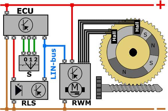
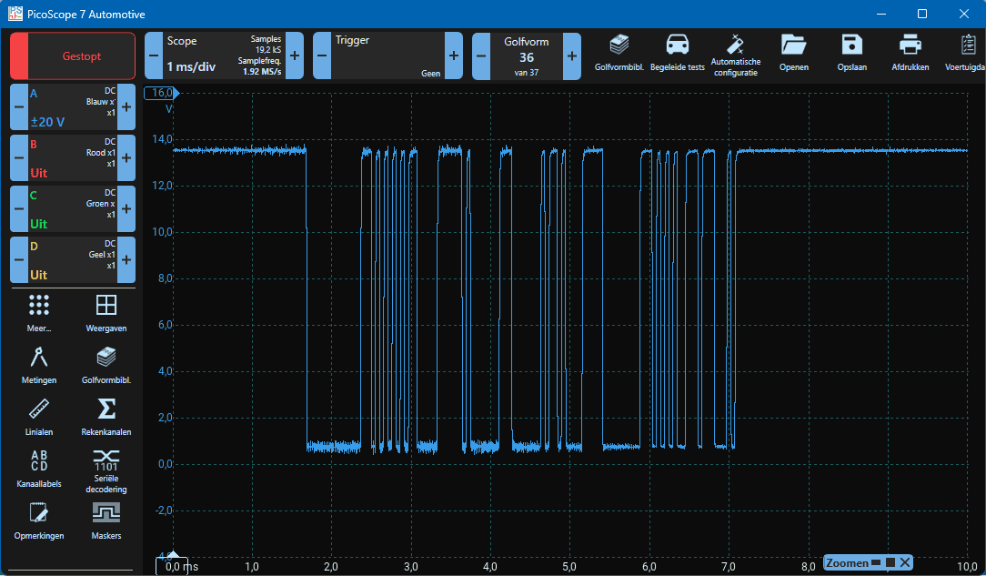
As already described, with LIN bus there is a master and one or more slaves. In the diagram above, the ECU (central electronics control unit) is the master, and the RLS (rain/light sensor) and RWM (wiper motor) are the slaves. In the oscilloscope image below, three signals can be seen that are placed one after the other on the LIN bus.
In each signal, the Break and Sync fields are clearly visible. In the following signals, it cannot be deduced where they come from or what exactly is being sent. What we do know is that in the Identification field the master indicates for which slave the message is intended. The ID field also indicates whether the slave must receive the message (Transmit frame) or whether the slave must send a message back, i.e. respond (Response frame). A Transmit frame could be that the slave must drive the actuator, such as switching the wiper motor on or off. With a Response frame, the master can request the current value of the moisture on the windscreen from the rain sensor. With this value, the master (the ECU) can determine at what speed the wiper motor must be controlled. The actual data that must be sent is placed in the Data fields. This could be, for example, the speed at which the wiper motor must be driven. Multiple data fields are possible.
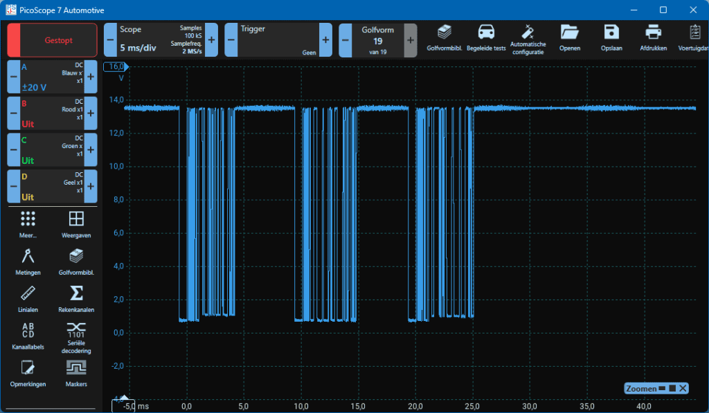
The oscilloscope image was taken with the wiper motor switched off and in a situation where no moisture is registered on the windscreen. Nevertheless, there is continuous communication between the master and the slaves. The ECU in the wiper motor recognises a change of one or more bits in this signal indicating that it must be switched on.
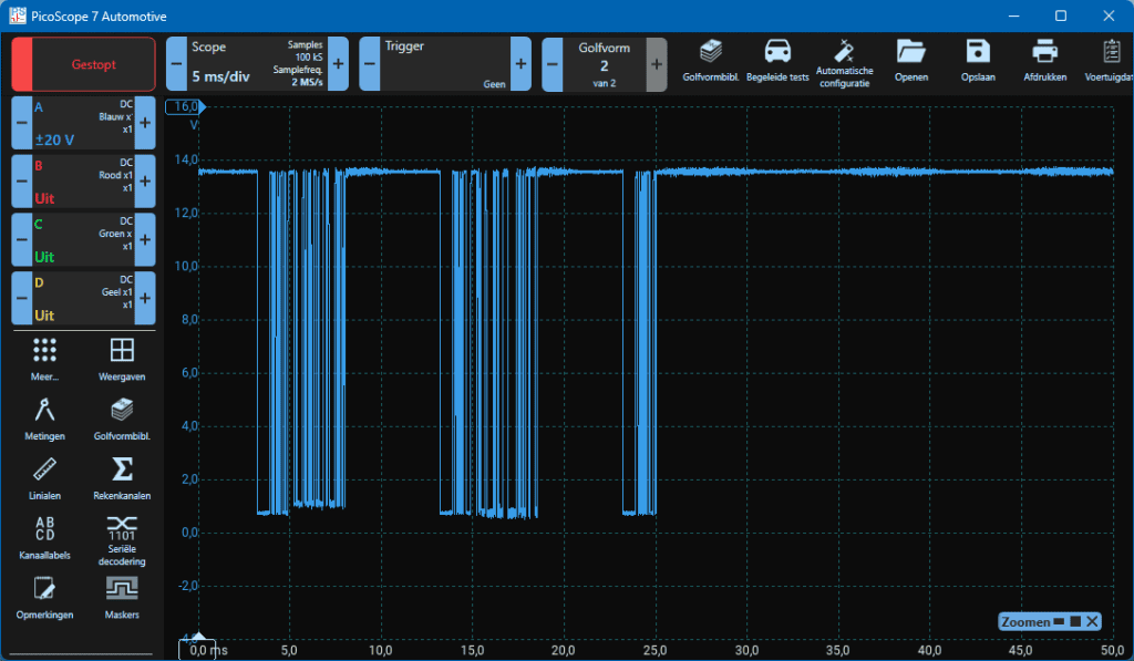
Malfunction in the communication with the wiper motor:
When the wiper motor is disconnected, the master tries to reach the slave. This can occur when the motor has a power supply problem, or when the LIN bus wire is interrupted. The master transmits the Break, Sync and ID fields with a Response bit, but the wiper motor does not respond.
In the oscilloscope image alongside, the third data frame shows that the master sends the data frame, but the slave does not respond. In that case, the master will store a DTC fault code relating to the communication problem. Such a fault code is indicated with U (User Network). It will also continuously attempt to reach the slave to resume communication.
In this case, measurements should be taken at the connector attached to the wiper motor. At the moment the LIN bus wire is interrupted, or the power supply (12 volts) or ground wire are interrupted, the wiper motor can no longer communicate either. A blown fuse is also one of the possibilities.
On the page: LIN-bus diagnosis several fault scenarios with solutions are described.
Related page: