Introduction:
A fault in LIN bus communication can cause multiple functions in the vehicle to fail or shut down entire control units because the whole network is taken down. When a LIN bus fault is suspected, the signal pattern can be measured and assessed with an oscilloscope. A multimeter is not sufficient for this, even though this diagnostic method is sometimes shown in how-to videos by mechanics. With a multimeter you can see:
- constant 12 volts -> no communication;
- constant 0 volts -> no communication;
- fluctuating voltage between 6 and 9 volts -> communication is probably taking place.
This diagnosis with the multimeter is inadequate. With an oscilloscope we can not only determine whether there is communication, but also whether all slaves respond to the master’s request frame and whether there is a transition resistance or interruption in a LIN bus wire.
How a LIN bus system works and how messages are structured is explained on the LIN-bus page. This page focuses on measuring the LIN bus with the oscilloscope and describes possible faults and causes.
The first paragraph, “Diagnosing LIN bus signals”, describes the most common fault patterns with their causes and solutions. Want to dive deeper into diagnostics? In the next paragraph, “Serial decoding”, the LIN bus signal with and without faults is analysed in detail.
Diagnosing LIN bus signals:
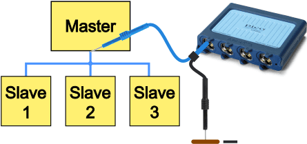
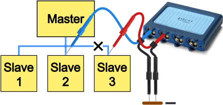
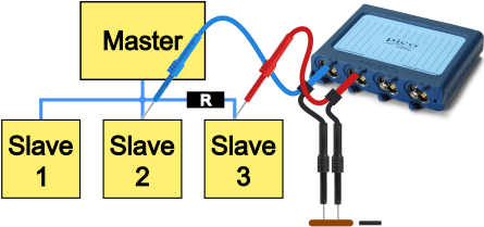
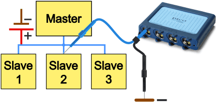
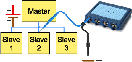
With an oscilloscope we can measure the LIN bus on one measurement channel relative to a ground point. The image on the right shows how the probes on channel A of the oscilloscope are connected:
- Blue probe: on the master or one of the three slaves;
- Black probe: on a good ground point.
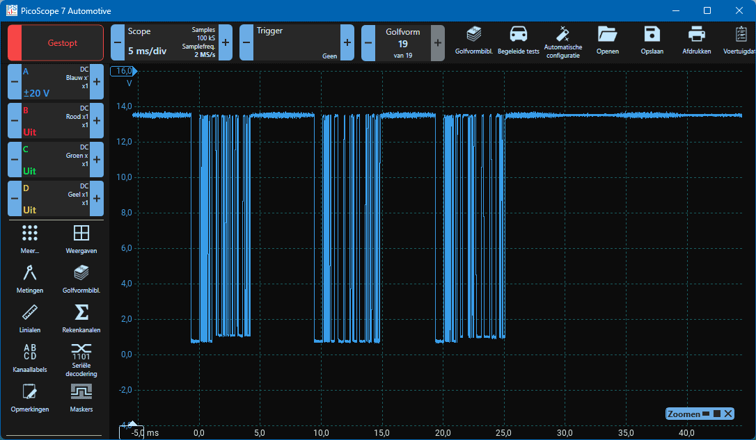
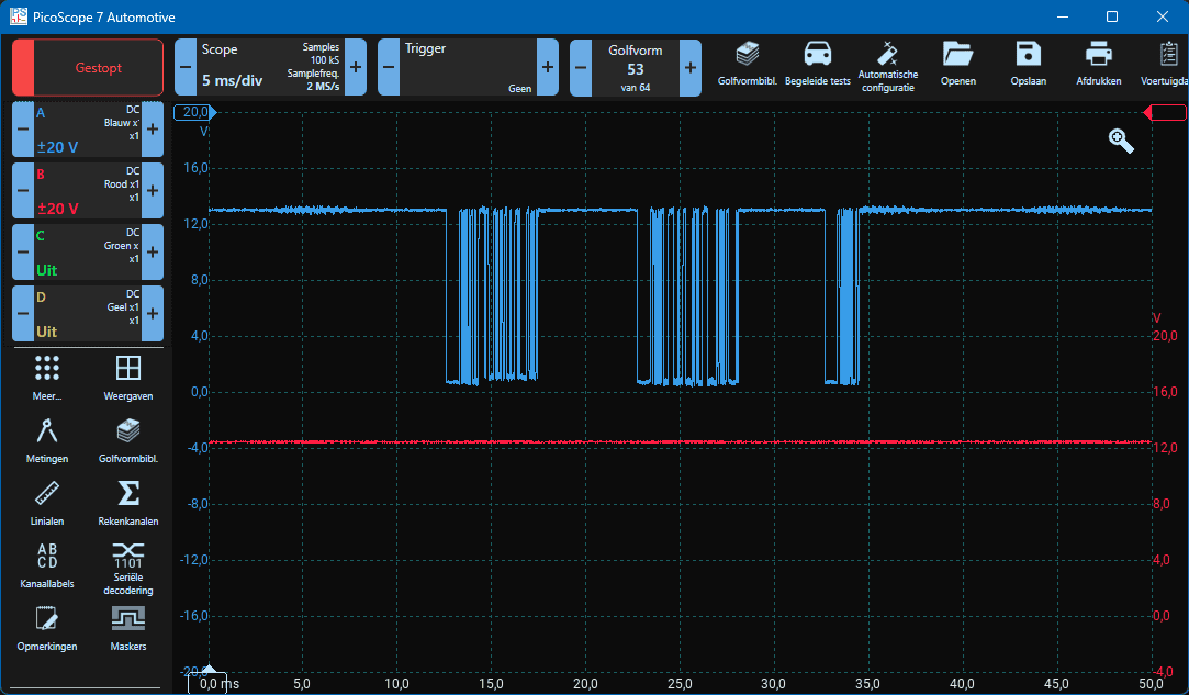
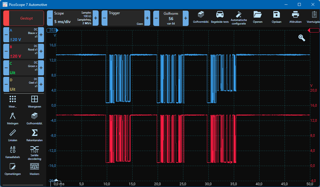
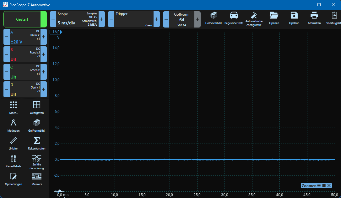
The oscilloscope image below shows a correct LIN bus signal. In the trace we see three data frames that keep repeating. The master is the body control module (BCM) and the slaves are the wiper motor, rain / light sensor and the wiper switch.
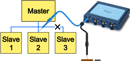
Slave does not respond (1):
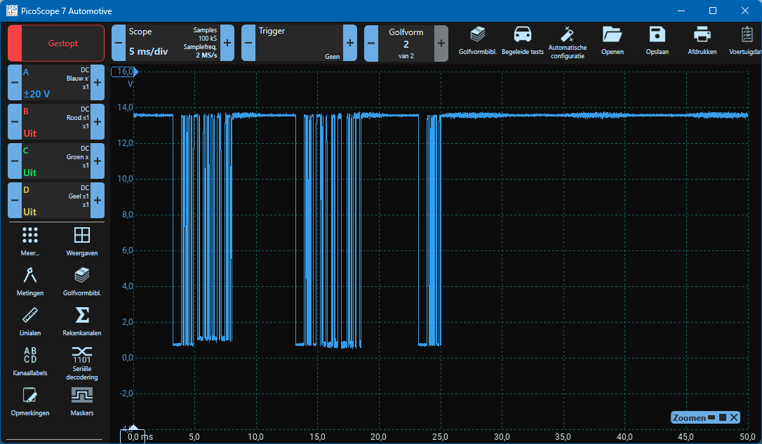
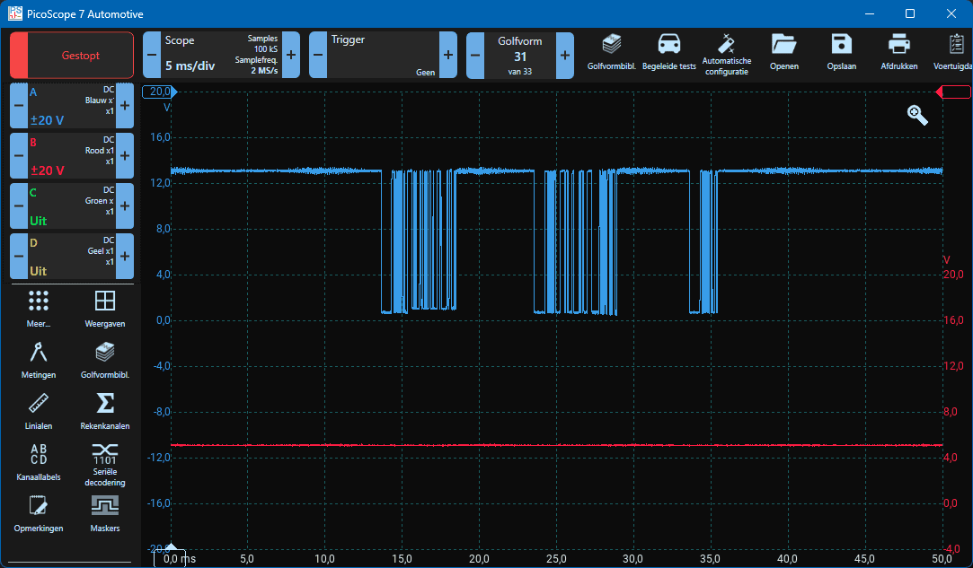
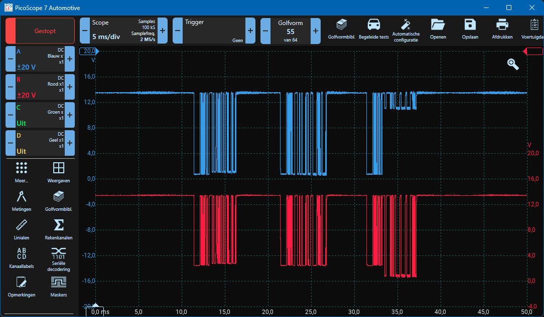
In the LIN bus signal we can see that the third data frame is considerably smaller than in the signal above. The master sets up the beginning of the message from the break time up to the request frame, and after that the signal remains between 12 and 14 volts. In this case the slave does not respond. This may be because the LIN bus wire between the master and the slave is interrupted, or because there is another reason why the slave does not send a response.
The fuse may be defective. If the slave does not receive supply voltage, it cannot respond. A broken positive or ground wire can also be causes.
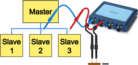
Slave does not respond (2):
Just as in the previous oscilloscope image, we are dealing with an interruption in the LIN bus wire to one slave. With a two-channel measurement, the voltage pattern up to the interruption (channel A) and what is measured on the slave (channel B) at the time of the fault are made visible. After inserting the backprobe into the slave’s connector, the voltage that the slave outputs is a constant 12 volts.
However, after the slave has not detected any activity for 10 seconds, the voltage drops to 5 volts. When reinserting the backprobe, the voltage again rises to 12 volts for 10 seconds, after which, due to inactivity of the LIN signal, it falls back to 5 volts. It is not known to me whether this voltage drop behaves the same on other LIN bus systems. It is possible that the voltage remains a constant 12 volts.
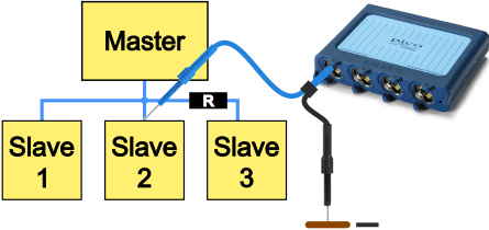
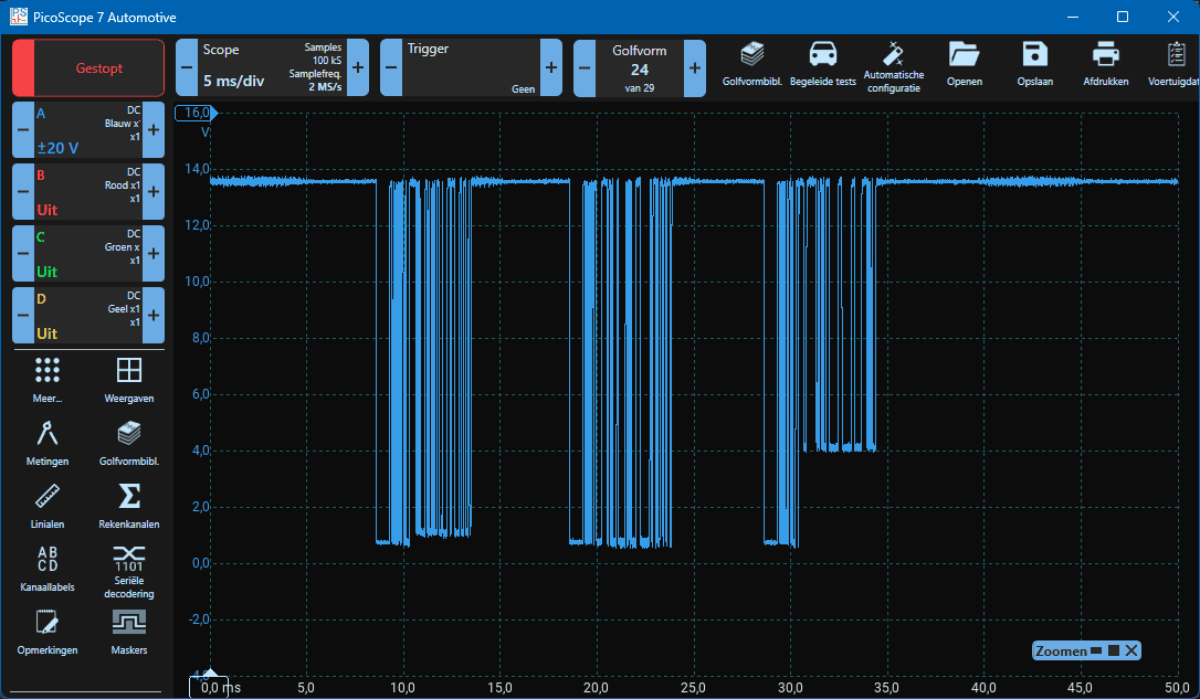
Transition resistance in LIN bus wire to slave (1):
A damaged wire can lead to transition resistance. If the LIN bus wire gets pinched or chafes through against a sharp part, the insulation can be damaged and the copper conductor can corrode. This causes a voltage drop, which is visible in the oscilloscope image below. In the third data frame the master sends a message to the slave, where the voltage drops to about 0.5 to 1 volt, which is normal. When the slave responds, the voltage does not drop further than 4 volts, indicating a transition resistance between the measuring point and the slave. This fault is simulated with a 330 ohm resistor. The worse the wire, the higher the transition resistance and the more the voltage rises.
Transition resistance in LIN bus wire to slave (2):
In the oscilloscope image below we again see the effect of a transition resistance, but this time the measurement is taken on the slave itself. The transition resistance affects all voltages that reach the slave from the master and other slaves via the resistor. This voltage does not drop below 2 volts. Because the probe is connected to the slave, we correctly measure the voltage (between 0.5 and 1 volt) that the slave sends. To make this measurement clear, the resistor is increased to 330 kilo-ohms. The 330 ohm resistor in the previous measurement was not sufficient to influence the signals that reached the slave.
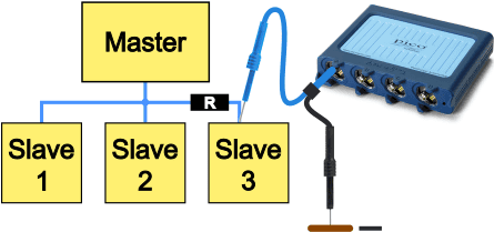
Transition resistance in LIN bus wire to slave (3):
The two oscilloscope images above relating to the transition resistance are shown here in the two-channel measurement. Channel A (blue) is connected on the harness side and channel B (red) on the slave side.
In this measurement a 330 ohm resistor has been inserted.
On channel A (blue) the voltage originating from slave 3 has risen to 4 volts. The voltage pattern on channel B (red) is virtually unchanged.
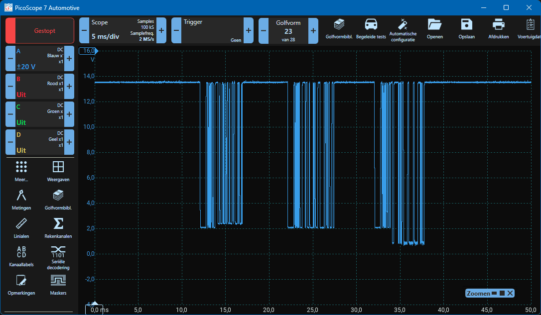
Transition resistance in LIN bus wire to slave (4):
With the same measurement setup as above, but with the resistor increased to 330k, we again see that the voltage on channel A rises sharply, and that the high resistance now also affects the voltage on channel B. The voltage originating from the master and slaves 1 and 2 has also increased on channel B as a result of the resistor.
No activity or short circuit to positive:
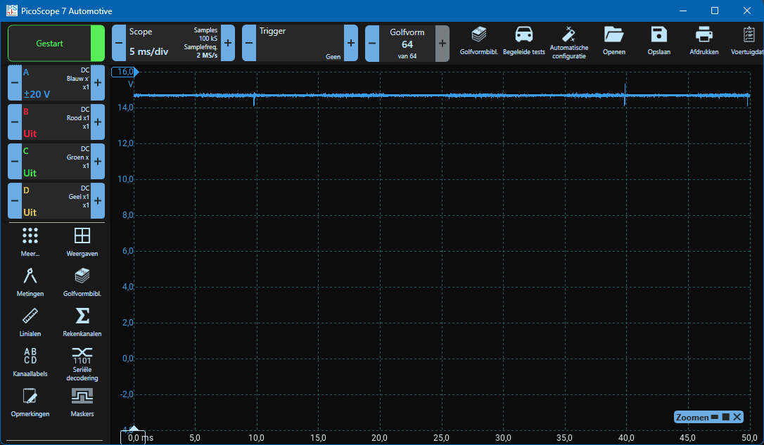
The voltage on the LIN bus wire is constantly between 12 and 14 volts, depending on system voltage. No communication is visible. Depending on the cause, slight ripple or noise may appear on this voltage line. The constant voltage line can have two causes: the master is not sending a signal so the slaves do not respond, there is a short circuit between the LIN bus and the positive, or the measurement is being taken on a slave that has no connection to the master and other slaves, e.g. due to a broken wire.
In the case of a short to positive, the cause may be in the wiring or in a slave. To locate the short circuit, the control units and/or connector plugs must be disconnected one by one. This will remove both the defective control unit and the cause of the short circuit. In that case, the LIN bus communication will be restored. If we measure on the master side or on a good slave, the oscilloscope image will show a data frame without a slave response, as shown in the first fault on this page.
LIN bus shorted to ground:
The LIN bus voltage is a constant 0 volts. As with a short to positive, in a short to ground the short circuit can be somewhere in the wiring harness or in a slave. By disconnecting slaves and/or connectors one by one, the cause can be removed and the LIN bus will immediately recover. Measurement must then be taken at a point where the master’s message arrives. For example: if we suspect a short circuit in a window motor and the connector in the A-pillar to the door is disconnected, we must measure on one of the other doors or at the master.
In this case, there is no point in measuring at the window motor in the disconnected door.
Serial decoding:
With the “serial decoding” function, the Picoscope software can analyze the measured LIN bus message, allowing us to dive deeper into the diagnosis.
Each data frame is divided into segments in which the break field, synchronization field, identifier, data fields, checksum and the interframe space are displayed with the duration and the corresponding hexadecimal values. With serial decoding the Picoscope can also estimate whether the LIN message is good enough to be processed by a master or slave.
Again we perform a two-channel measurement. We place the test leads of channels A and B on different measuring points, because in the next measurement we will introduce a resistor between these points.
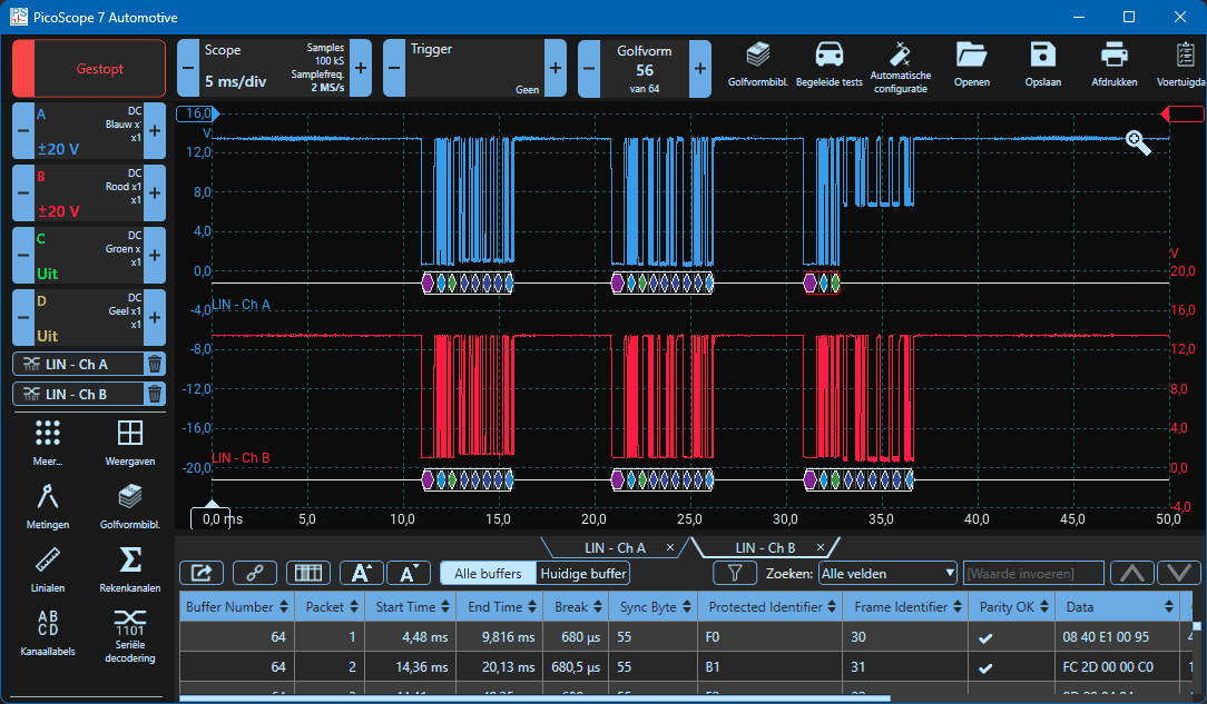
Below the data blocks we see a horizontal white line with markings underneath:
- Break field: purple
- Sync field: light blue
- Identifier field: green
- Data blocks: dark blue
- Checksum: blue
Each message has the same structure and ending, but the content differs due to the amount of information sent in the message. The first message contains four dark blue data blocks and in the second and third we see five data blocks.
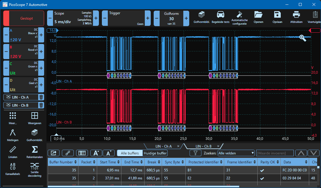
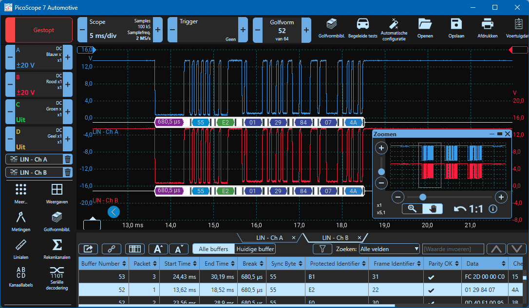
To understand the serial decoding even better, the view is zoomed in on the first message with four data blocks. This also creates space in the white decoding area to display the time (break field) and the hexadecimal values (the rest) below the different parts of the message. Below the scope display, a table appears containing all the data blocks with times and hexadecimal values. A check mark (V) appears next to “parity OK” when this part of the message has been transmitted correctly and can be processed by the ECUs.
Transition resistance in LIN bus wire to slave:
As in the previous paragraph, a transition resistance is installed between slave 2 and 3, where, by means of a two-channel measurement, the voltage development on both sides of the resistor is measured. This time we add the serial decoding to it.
The resistance has been increased to approximately 500 ohms, causing the voltage in the measurement on channel A to rise from slave 3 to approximately 5 volts.
Serial decoding can still be performed. No errors are visible. Despite the presence of a transition resistance, the signal can still be read by the ECUs. No incorrect message will be interpreted due to this transition resistance, and no fault codes will be stored.

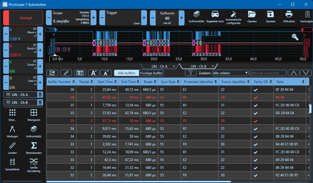
When increasing the resistance, the voltage rises to 7 volts. Under the slave section of the third message, all data and checksum markings are missing from the identifier field onwards. The first blocks (break, sync, id) sent by the master are also outlined in red. This indicates that the message is incorrect. The information sent by the slave can no longer be read by the master and other slaves in the network.
In the table with the times, identifiers and hexadecimal values, it can be seen that “frame identifier 30” is colored red. There are more red lines in the table. All red lines correspond to the red outlined sections in the scope image above.
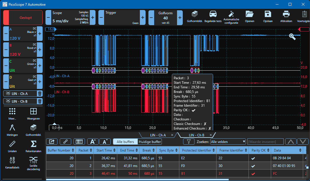
When the data frame is clicked, a menu with information expands. Here we see data corresponding to the table: Protected identifier B1 / frame identifier 31, data missing, checksum missing and enhanced checksum failed (x).
Related page: