Introduction operational amplifier:
Op-amp stands for operational amplifier. Operational amplifiers are used in integrated circuits (such as on PCBs in computers) with a very high gain factor, with which the input voltage (e.g. from a sensor) is amplified. The amplified signal is then suitable as an input signal for a control unit, such as the ECU. The gain factor can be 100,000 or more.
By means of resistors, the gain factor can be reduced so that the output voltage can never exceed the (predefined) maximum value.
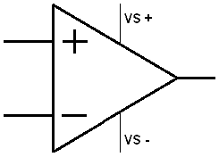
The image shows the symbol of an op-amp. The terminals VS + and VS – are often omitted.
When a voltage difference occurs across the op-amp and the voltage at the + is greater than at the -, the output voltage is amplified. Conversely, when the – is greater than the +, the output voltage is amplified negatively. This can be used intentionally with an inverting amplifier. With an inverting amplifier, the output voltage will be negative. The plus and minus signs in the image of the op-amp will also swap. As the op-amp is shown now, it is a non-inverting amplifier. The output voltage will be positive.
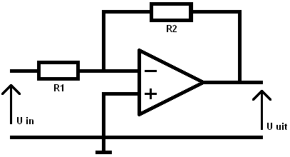
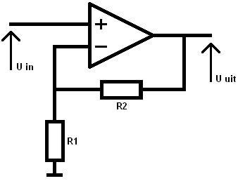
Inverting op-amp:
The positive input of the op-amp is connected to ground. The positive voltage is therefore always 0. The resistor values determine the gain factor (A). The voltage “U in” can be a sensor signal that is amplified for the ECU, which is connected to the output U out.
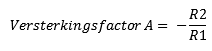
For an inverting op-amp, the gain factor can be calculated with the following formula:
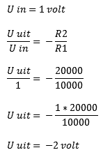
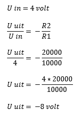
A calculation example now follows with U in = 1 Volt and U in = 4 Volt. By multiplying the fractions crosswise, the voltage U in is multiplied by the gain factor. This is used to calculate the output voltage (U out).
When the gain factor is increased (for example to 100), you will see that with a minimal increase of U in, U out rises very rapidly. Never forget that the output voltage of the inverting op-amp is negative.
R1 = 10kΩ = 10000Ω
R2 = 20kΩ = 20000Ω
Non-inverting op-amp:
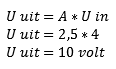
The non-inverting op-amp can be compared with the inverting op-amp. The difference is, as the name already suggests, that this op-amp does not invert (reverse) the voltage. The output voltage is therefore positive. We perform the following calculation in the simple way, by multiplying the gain factor A by the input voltage.
R1 = 10kΩ = 10000Ω
R2 = 20kΩ = 20000Ω
Difference / differential amplifier:
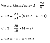
The difference / differential amplifier compares the two input signals (U in 1 and U in 2) and then amplifies the difference. In the image below the voltages U in 1 and U in 2 are compared. These are 2 and 4 Volts. The difference between them is 2 Volts. This is amplified with the gain factor, which depends on the resistor values R1 and R2:
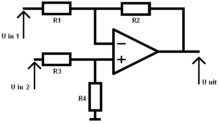
U in 1 = 2 Volts
U in 2 = 4 Volts
R1 = 10kΩ
R2 = 20kΩ
R3 = 10kΩ
R4 = 20kΩ
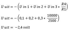
Inverting summing amplifier:
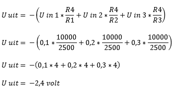
The inverting summing amplifier can be calculated in 2 ways. The easiest way is when the resistors R1, R2 and R3, as in the example, all have the same resistance values (method 2). If these resistors are unequal to each other (for example if R1 has a different value than R2 and R3), then method 1 must be used:
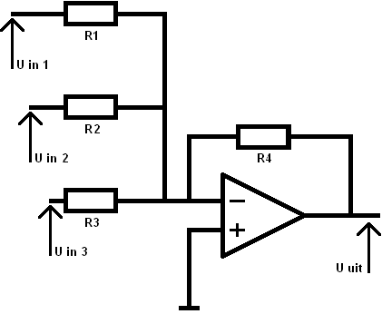
U in 1 = 0.1 Volt
U in 2 = 0.2 Volt
U in 3 = 0.3 Volt
R1 = 2.5 kΩ
R2 = 2.5 kΩ
R3 = 2.5 kΩ
R4 = 10 kΩ
Method 1 (R1, R2 and R3 are not equal to each other)
Method 2 (R1, R2 and R3 are equal to each other)