Introduction:
In hydraulic installations it is in most cases important to be able to control the movement speed of hydraulic cylinders or the hydraulic pump. For this purpose, a hydraulic pump with a variable displacement can be used. However, that is very complex and expensive. A simple and inexpensive way to achieve such control is by using restrictions and flow control valves. By creating a constriction in the supply or return line of the cylinder or motor, the volume flow is throttled. The line is thus pinched, so that the fluid can flow through it with a reduced volume flow.
Restriction:
With a restriction control we obtain a constriction in the line. This can be compared to a tap that lets water flow; the further you open or close the tap, the greater or smaller the water output will be.
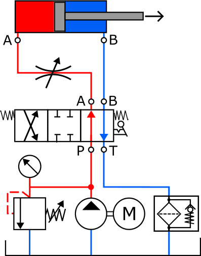
In the following diagram, the restriction is located in the supply line between the directional control valve and the cylinder. The arrow in the restriction indicates that it is variable: the restriction can be set manually.
In the line before the restriction, the pressure created by the hydraulic pump prevails. This is the maximum system pressure. After the restriction, the pressure is considerably lower. The pressure energy is lost in the restriction and converted into heat. The volume flow that is held back by the restriction is discharged to the return line via the pressure relief valve. The restriction causes a reduction of the volume flow in both the extending and retracting stroke of the piston. This is not always desirable. More about this later.
To gain insight into the system pressures, here is an example of the pressure differences that a restriction can cause:
- pump output = 10 l/min;
- restriction is set to 8 l/min;
- volume flow discharged through the pressure relief valve = 2 l/min.
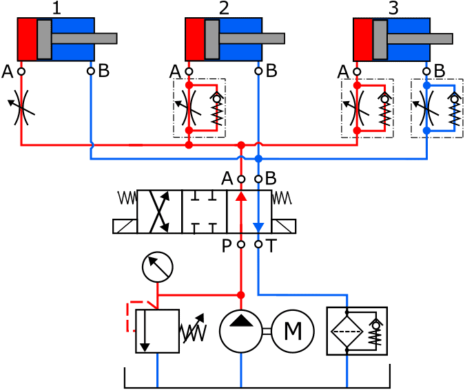
A hydraulic cylinder can be equipped with a volume-flow-controlling restriction in three main ways. The image below shows a solenoid-operated directional control valve and three cylinders. Each cylinder has a different restriction control:
- this cylinder has a variable restriction on the supply line. In both the extending and retracting movement, the fluid flow is throttled. The extending and retracting movements of the piston rod proceed at the same speed;
- the restriction with spring-loaded check valve ensures that the extending movement of the piston is braked. However, during the retracting movement, the fluid flow pushes the check valve open, allowing the fluid to flow back to the return via both the restriction and the check valve. The extending stroke therefore takes place more slowly than the retracting stroke;
- with a restriction and check valve on both the supply and return line, the piston speed can be adjusted the most accurately: when the piston moves, the restriction actually determines the fluid flow to the cylinder. On the other side the fluid can flow back to the reservoir without encountering resistance.
Flow control valve:
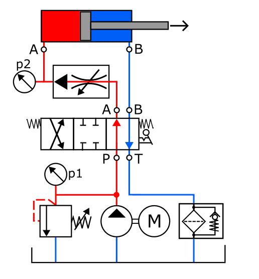
In hydraulic systems in which the movement speed of the cylinders or hydraulic motors must remain constant despite a varying load, flow control valves are used. In the following diagram we see, among other things, a series flow control valve and two pressure gauges.
The pressure that can be read from p1 depends on the pressure relief valve, which returns part of the hydraulic pump output to the return line. The pressure p2 is determined by the load on the piston: when it is subjected to more counterforce during the extending stroke, the pressure p2 increases.
The flow control valve is adjustable and makes it possible for the volume flow to the cylinder to remain constant, regardless of pressures p1 and p2.
The operation of the flow control valve is as follows: the pressure drop (Δp) across the restriction in the flow control valve is continuously measured. As soon as a pressure change occurs, the flow control valve adjusts the size of the restriction. The pressure control valve ensures that the pressure drop across the restriction, and thus the fluid flow, remains constant at all times.
Related page: