Introduction:
The braking system of a truck has three main functions: reducing speed, bringing the vehicle to a stop, and keeping it stationary when parked. It differs from a passenger car in that it uses pneumatics instead of hydraulics. The brakes are actuated by air from the pedal and the parking brake lever.
Heavy commercial vehicles and mobile machinery have air pressure brakes, with subsystems consisting of:
- service brake
- emergency brake (auxiliary brake)
- parking brake
- continuous brake.
The first three subsystems are prescribed by law.
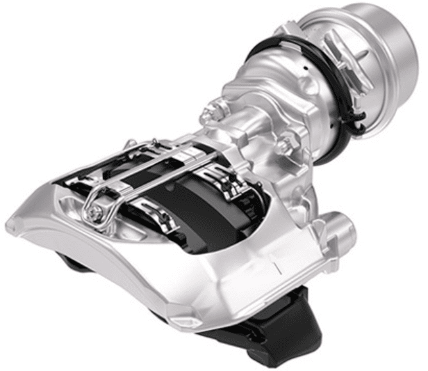
The service brake allows you to reduce the vehicle’s speed or bring it to a stop. Operated by foot, you must be able to modulate the braking force. Service brakes are friction brakes, which not only provide deceleration, but also cause wear on brake linings, brake discs and brake drums. Wheel brakes convert part of the kinetic energy into heat (friction heat) and thus slow the vehicle down.
The emergency brake must ensure that braking is still possible if the service brake fails. The parking brake locks a stationary vehicle to prevent it from rolling away and operates mechanically, as required by law. It is operated with the parking brake lever on the dashboard, which can also serve as a parking brake. The parking brake is used to hold the parked truck in place and, by law, operates mechanically by fully venting the spring brake cylinders.
In addition to an air brake system, commercial vehicles usually also have a continuous brake system. Continuous brake systems, such as the retarder (engine brake), hydrodynamic retarder (driveshaft brake), and electromagnetic retarder (also a driveshaft brake), are auxiliary braking systems that reduce speed without bringing the vehicle to a stop, and without thermally (over)loading the mechanical brake components, when descending a mountain.
Air vs. fluid:
Passenger cars and light commercial vehicles usually use a hydraulic braking system with brake fluid. In heavy commercial vehicles, such as trucks and buses, the braking forces and heat generation during braking are much greater. Therefore, larger brake components are used, such as larger brake drums and wider brake linings. A larger surface area of the brake lining helps to distribute heat better and reduce wear.
To operate these large brakes hydraulically, a large volume of brake fluid would be required. This results in a longer pedal travel and a less direct pedal feel. That is why a full air brake system is usually used in heavy commercial vehicles. In this system, air pressure is used to generate high braking forces and to operate multiple axles or trailers simultaneously.
A hydraulic brake system theoretically responds faster than an air brake system, because brake fluid is virtually incompressible. In air brake systems this delay is limited by a high system pressure and the use of relay valves located close to the brake cylinders.
Air supply, air consumption, parking brake and the components:
The service brake of a truck consists of an air-supplying and an air-consuming section. In the illustration, the parts belonging to these sections are colored blue and yellow.
Air-supplying section:
The air-supplying section ensures that air is delivered at the correct pressure. In this section, the air is also cleaned and dried. The components that form the air-supplying section and are indicated in blue in the illustration below are:
1. Air compressor: the air compressor contains two cylinders in which air is drawn in and then fed under pressure to the next component;
2. Air dryer: moisture is removed from the compressed air here. The filter contains pellets that absorb the moisture. Under the dryer is the wet reservoir;
3. Four-circuit protection valve: when a leak occurs in one of the three circuits, the air pressure in the two other circuits is maintained;
4 to 6. Air reservoirs: the air supply is stored in the air reservoirs.
Air-consuming section:
In the air-consuming section, the air from the air-supplying section is used. This section contains the actuation, as well as the controls that adjust the brake pressure according to the load, and of course the brakes themselves. The air-consuming section is colored yellow.
7. Foot brake valve: the position of the foot brake valve determines how much air is admitted to the brake cylinders. The driver operates the foot brake valve;
8. Load-sensing valve: the weight (load) on the rear axle is registered (mechanically or pneumatically). The ALR controls the relay valve;
9. Front diaphragm cylinders: the brake calipers of the front wheels are actuated with diaphragm cylinders.
10. Rear diaphragm cylinders: the brake calipers or brake drums of the rear wheels are actuated by the diaphragm cylinder, which is located in a combined spring brake cylinder.
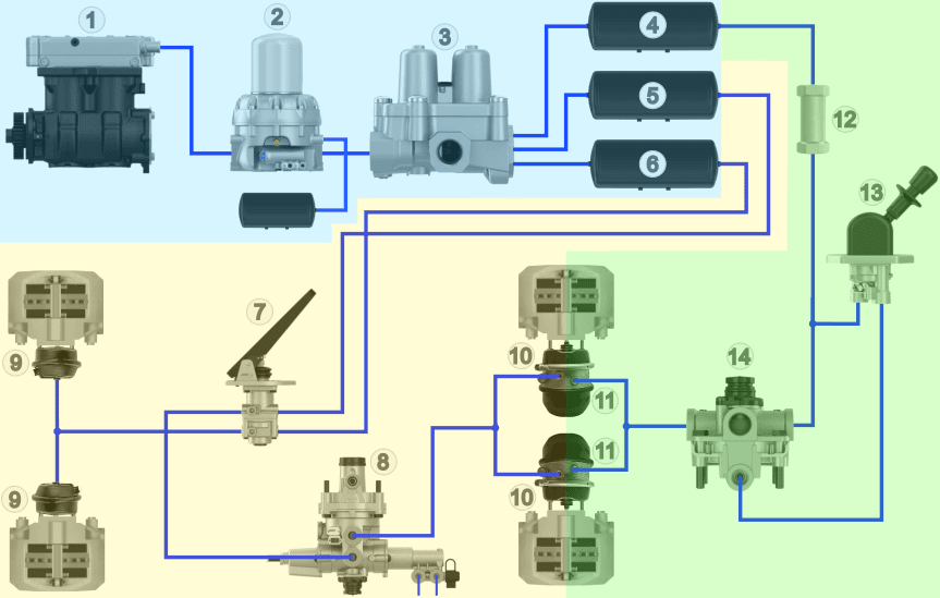
Legend:
1. Air compressor
2. Dryer with wet reservoir
3. Four-circuit protection valve
4. Air reservoir circuit 3
5. Air reservoir circuit 1
6. Air reservoir circuit 2
7. Foot brake valve
8. Load-sensing valve (ALR)
9. Diaphragm cylinders (front)
10. Diaphragm cylinders (rear)
11. Spring brake cylinders (rear)
12. Check valve
13. Parking brake valve
14. Relay valve
- Blue: air-supplying
- Yellow: air-consuming
- Green: parking brake / emergency brake
Parking brake and emergency brake:
In addition to the air-supplying and air-consuming sections, we also see the parking and emergency brake section in green. When the truck is parked, the driver can operate the parking brake. In an emergency, the emergency brake can be activated to bring the vehicle to a stop. The following components are found in the parking and emergency brake section:
11: Spring brake cylinder: at rest, without air pressure, the spring in this combined spring brake cylinder keeps the vehicle braked;
12: Check valve: this ensures that the brakes do not start dragging if a leak occurs in circuit 1, 2 or 4;
13. Parking brake valve: this lever is located within hand’s reach in the dashboard. With this lever the parking brake can be (de)activated;
14. Relay valve: the air volume from the parking brake valve determines the flow from reservoir 4 to the spring brake cylinders 11.
Circuits in the air brake system:
There are three circuits in the air brake system of a truck:
- circuit 1: rear brakes
- circuit 2: front brakes
- circuit 3: parking brake / emergency brake
- circuit 4: accessories such as engine brake, air horn and cab suspension
- circuit 5: air suspension. Previously, the air suspension was connected to circuit 4. In new vehicles, this circuit is tapped off before the valve due to a higher pressure and a fast response time.
The image below shows the three circuits of the braking system, which are separated in the four-circuit protection valve. The service brake consists of circuit 1 (blue for the front axle) and circuit 2 (red for the rear axle). Both circuits have their own air reservoirs (5 and 6 in the image), with an air pressure of approximately 10 bar. The parking brake / emergency brake (green) has its own air reservoir (4). The air pressure is approximately 8 bar.
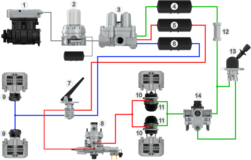
Legend:
Circuit 1: Red
Circuit 2: Blue
Circuit 3: Green
This overview does not yet include a trailer brake valve, because on this page we first focus on the basics of the air brake system of the truck. On the page: trailer brake the diagram above is expanded with, among other things, the trailer brake valve, the associated components and additional air lines.
Air brake codings:
The air brake system of a truck consists of several circuits, such as the service brake, parking brake, accessories and air suspension. When a trailer (drawbar trailer) is coupled, one circuit of the brake system is extended. During maintenance, repair or troubleshooting it is important that the correct components and lines are found. To keep things clear, all inlets and outlets of the valves are provided with codings. These codings show where the line comes from and where it goes. The codings can be found in line diagrams and function diagrams.
0: Suction connection air compressor
1: Air supply (inlet) to a component
2: Air discharge (outlet) from one component to another
3: Vent / blow-off opening to the outside air
4: Control connection of a relay function of a valve
5: Free (often used from an air spring at EBS of a trailer)
6: Free
7: Frost protection
8: Lubricating oil (81: supply, 82: return)
9: Coolant (91: supply, 92: return)
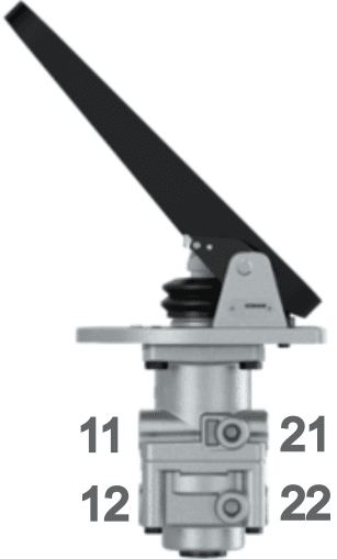
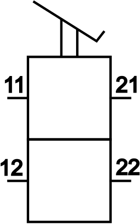
A component can have multiple inlets and outlets. The coding then consists of two digits, the first indicating the type of connection and the second the sequence number. The foot brake valve, for example, has two inlets and two outlets for circuit 1 (front axle) and 2 (rear axle).
- inlet circuit 1: 11
- inlet circuit 2: 12
- outlet circuit 1: 21
- outlet circuit 2: 22
The following images show an illustration of a foot brake valve (drawing: Wabco) and the symbol of a foot brake valve, both with the codings.
In the images below we see the diagram of the air brake system with all components (top) and the diagram with the same layout in which the separated circuits with all symbols and codings of this particular brake system are shown (bottom).
Legend:
1. Air compressor
2. Dryer with wet reservoir
3. Four-circuit protection valve
4. Air reservoir circuit 3
5. Air reservoir circuit 1
6. Air reservoir circuit 2
7. Foot brake valve
8. Load-sensing valve (ALR)
9. Diaphragm cylinders (front)
10. Diaphragm cylinders (rear)
11. Spring brake cylinders (rear)
12. Check valve
13. Parking brake valve
14. Relay valve
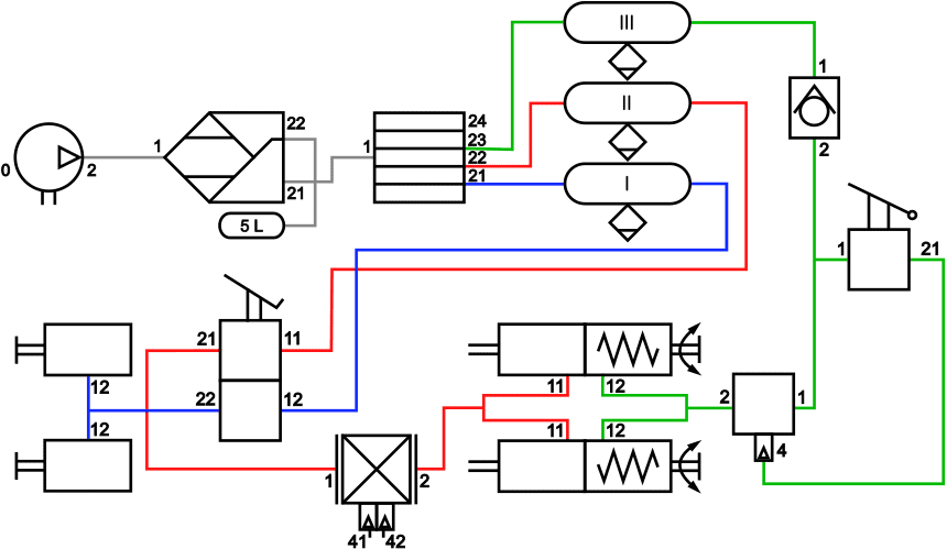
Legend:
Circuit 1 (rear brakes): Red
Circuit 2 (front brakes): Blue
Circuit 3 (emergency brake / parking brake): Green
Related page: