Air supply introduction:
In the air supply system, air is drawn into the compressor and compressed to the desired pressure. The compressed air is then cleaned and dried in the air dryer, so that as little moisture as possible is carried to the components in the braking system. The four-circuit protection valve distributes the air over several circuits, and when a leak occurs in one of these three circuits, it protects the intact circuits against a drop in pressure.
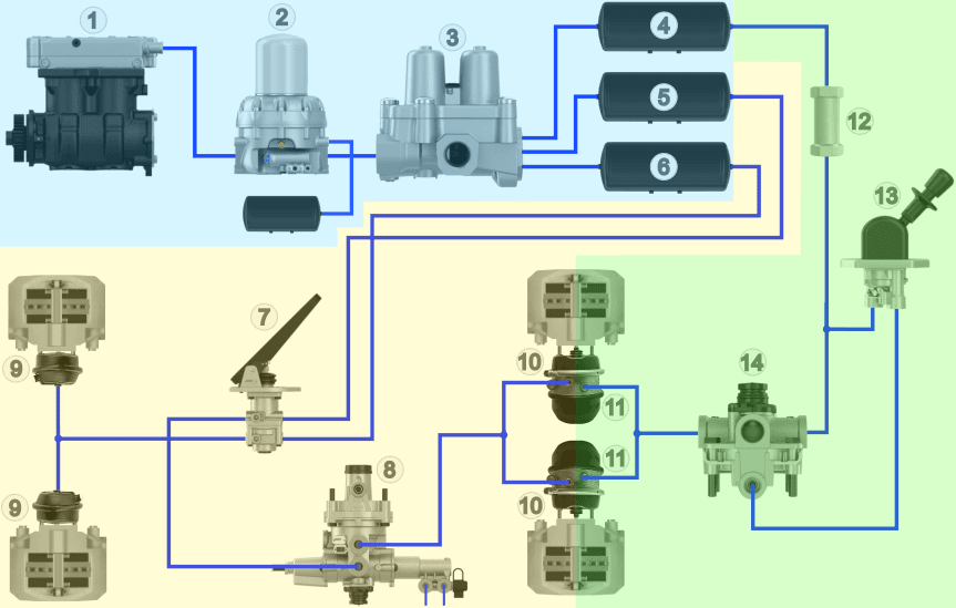
The image below shows several parts of the air brake system of a truck, where the components in the blue section belong to the air supply section.
Legend:
1. Air compressor
2. Dryer with wet tank
3. Four-circuit protection valve
4. Air tank circuit 3
5. Air tank circuit 1
6. Air tank circuit 2
7. Foot brake valve
8. Load-sensing valve (ALR)
9. Diaphragm cylinders (front)
10. Diaphragm cylinders (rear)
11. Spring brake cylinders (rear)
12. Non-return valve
13. Parking brake valve
14. Relay valve
- Blue: air supply
- Yellow: air consumption
- Green: parking brake / emergency brake
On this page, the air supply section indicated in blue, with the compressor, dryer, four-circuit protection valve and the air tanks, is discussed.
Air compressor:
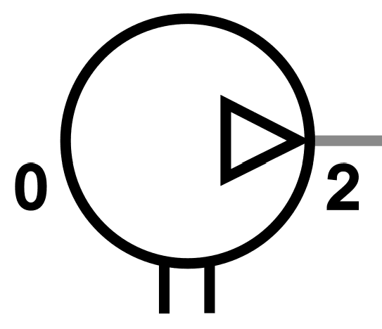
The air compressor of vehicles with air brakes is driven from the combustion engine via a gear transmission. The input motion drives the crankshaft in the compressor. The connecting rod causes the piston to move up and down, drawing in atmospheric air during the downward stroke. The drawn-in air (port 0) is compressed by the piston, after which this compressed air is routed via the pressure valve and port 2 to the tanks.
The air compressor, mounted on the engine, consists of various components, including the drive gear, the oil seal, the crankshaft, the pistons, the cylinders, the intake valve, the exhaust valve and unloading valves. These components work together to supply air, compress it and store it in the air tanks.
The air compressor can have different designs, such as single- or multi-cylinder, and can be driven by the engine or electrically. Electric and hybrid vehicles often use an electrically driven air compressor. Maintenance of the air compressor often includes lubrication, using engine oil lubrication systems, and cooling, which can take place via the engine’s cooling system or a separate cooling circuit for electrically driven compressors.
To prevent the system pressure from becoming too high, excess air pressure is vented by a pressure regulator and blow-off valve, integrated in the air dryer housing. When the desired pressure is reached, the compressor can be switched off to save fuel. Unloading valves ensure that the compressor no longer builds pressure once the desired pressure has been reached.
In situations where the pressure can become dangerously high, a safety valve is used to relieve the pressure. A two-stage compressor can be used to further reduce fuel consumption by building up the pressure in two stages, which improves the compressor’s efficiency.
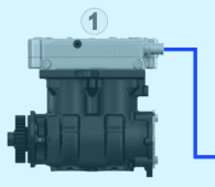
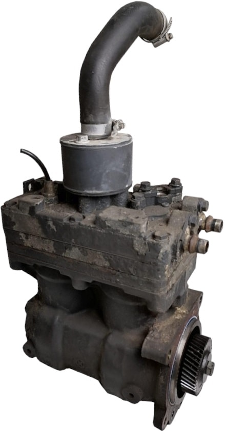
The images below show the air compressor and the installation position on a Scania DC12.
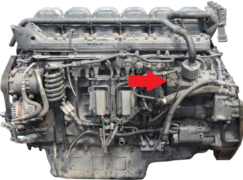
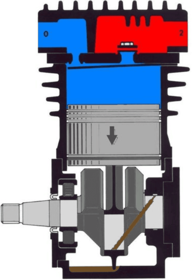
The crankshaft in the air compressor is driven via a gear transmission. With the engine running, the piston in the compressor moves up and down. During the downward stroke, a vacuum is created in the cylinder chamber (blue), causing the intake valve to open so air can flow into the cylinder chamber. The vacuum in the cylinder chamber keeps the exhaust valve closed.
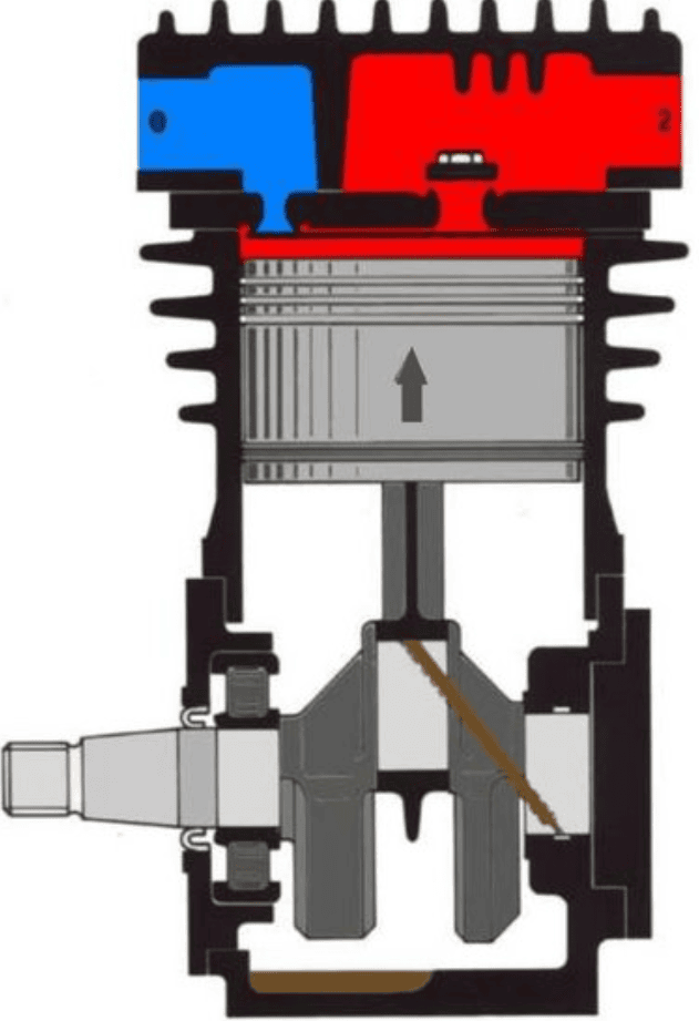
When the piston moves upward, the air is compressed (red) and an overpressure is created in the cylinder chamber, causing the intake valve to be forced closed and the exhaust valve to open. The air is forced past the exhaust valve to the air tanks.
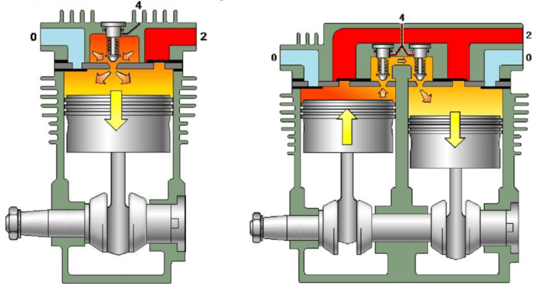
The air compressor of a truck can be designed with two cylinders. The crankpins are offset 180 degrees, so the direction of movement is opposite. The images below show a compressor with one cylinder (left) and with two cylinders (right).
Air dryer:
The air supplied by the compressor contains moisture (water vapour). When the water vapour condenses, water is formed, which can cause corrosion in components such as air tanks, valves, brake cylinders and lines, especially when freezing. In addition, oil particles from the air compressor and dust particles from the intake air can end up in the compressed air. To prevent this, an air dryer is necessary to filter moisture, oil and dust particles from the air.
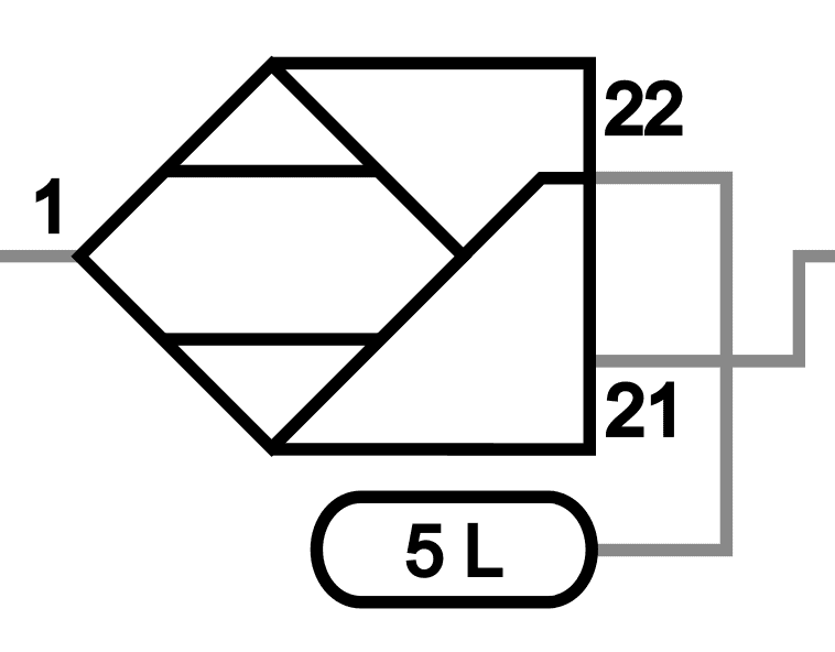
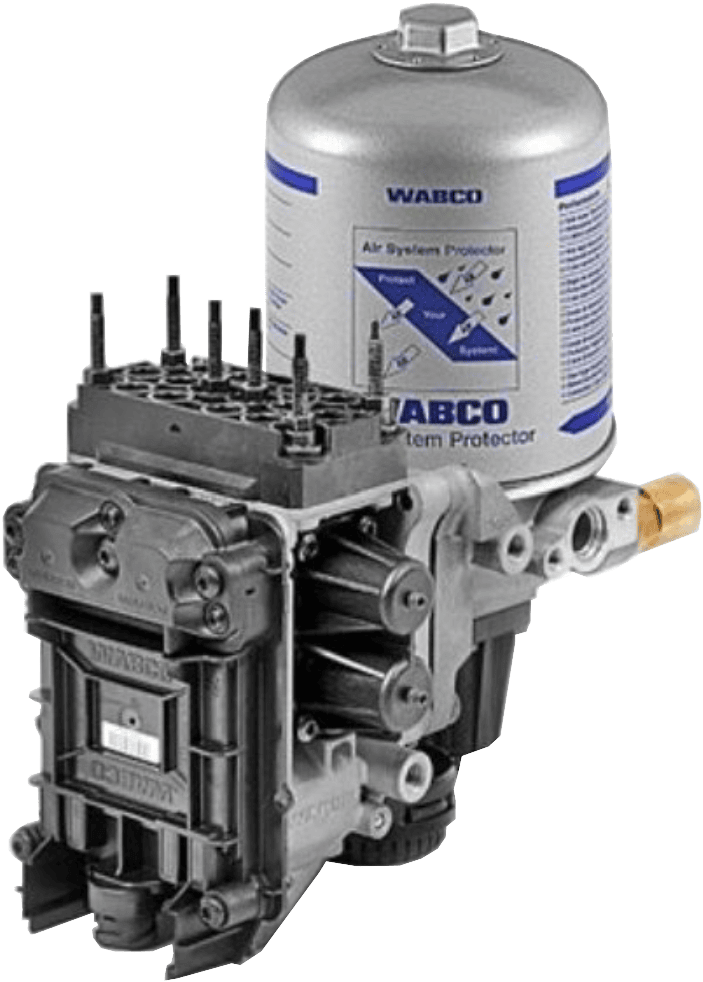
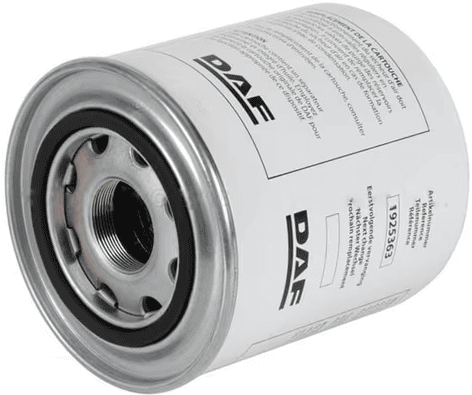
In the following image, the air dryer (with the blue background, from the overview of the air supply section) is shown together with the symbol with codings beside it.
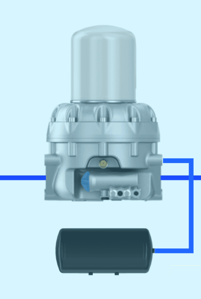
A pressure regulator is often integrated in the air dryer. As soon as the maximum system pressure is reached, air is discharged via the blow-off valve, with the water contained in the dryer also being expelled.
The air dryer is usually mounted on the vehicle chassis, between the expansion line / cooling line and the four‑circuit protection valve.
The air dryer consists of several components: the dryer housing, desiccant cartridge, inlet, outlet and heating element. There are also air dryers with a different type of cartridge, where the dryer housing and desiccant cartridge are combined.
The operation of the air dryer involves passing compressed air through a filter where dust and other dirt are retained, while moisture and oil particles are guided into a chamber with granules (desiccant cartridge) to be absorbed. The granules in this cartridge are hygroscopic, which means they easily attract moisture. The air is passed through various chambers in the air dryer, where the moisture is removed by the granules. The desiccant cartridge has a limited capacity to absorb moisture. Therefore, the saturated cartridge needs to be replaced or regenerated regularly.
During regeneration, a small amount of air flows in the opposite direction through the desiccant cartridge to absorb moisture, after which the moist air is blown outside and the collected water is drained from the air dryer housing. Despite regular regeneration of the granules, the drying capacity gradually decreases due to saturation with oil mist and dirt, which is why the cartridge must be replaced periodically according to the manufacturer.
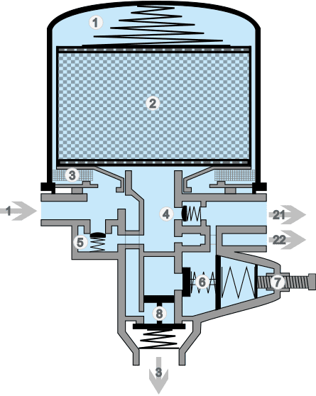
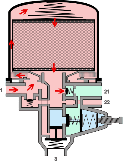
The image below shows a cross-section of an air dryer with internal pressure control. Below this image, the situations in which the pressure is built up, regulated and the regeneration of the filter element are described.
Legend:
1. Air dryer element
2. Drying element with granules / desiccant
3. Coarse filter
4. Check valve
5. Bypass valve
6. Pressure control valve
7. Adjustment of pressure control valve
8. Blow-off valve
-> 1. Inlet air dryer from compressor
-> 21. Outlet 1 to four‑circuit protection valve
-> 22. Outlet 2 to wet air reservoir
-> 3. Venting / blow-off opening
Building pressure:
Compressed air from the air compressor enters the air dryer at connection 1. The air is directed through the drying element via the coarse filter. In the images below, the airflow is shown with the red arrows. The air pressure opens the check valve. At a certain air pressure, the check valve opens against the spring force, and the air flows via outlet 21 to the four‑circuit protection valve.
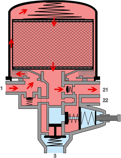
Limiting pressure:
Inside the air dryer there is a pressure regulator that ensures that the pressure cannot rise too high. The air pressure in the channel after the check valve (at outlet 21) exerts a force on the diaphragm of the pressure limiter. The diaphragm is pressed in against the spring force, causing the hollow plunger to move to the right. The hollow space is closed and the air reaches the space above the blow-off valve. The airflows responsible for this are indicated with the white arrows.
The incoming air pressure also exerts a force on this blow-off valve, causing it to open as well against the spring force.
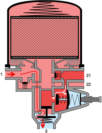
The air compressor will move the air directly from connection 1, via the channels in the air dryer, to connection 3. The dryer is now without pressure. The compressor will move air without building pressure. The cut-in pressure is 1 to 1.5 bar lower than the cut-out pressure, to prevent the pressure regulator from constantly switching on and off. The moment of switching on and off is called hysteresis, just as in electronics.
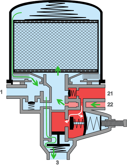
Regeneration:
At the moment the pressure is limited, the blow-off valve opens and the pressure in the air dryer drops. In the regeneration tank (connected to outlet 22) there is still a small reserve of air at system pressure. The regeneration tank empties via the bore in the dryer and the restriction, and blows dry and slightly heated air in the opposite direction through the filter element. The dry air will draw the present moisture from the granules and thereby dry the granules. The moist air will be discharged to the atmosphere via the coarse filter and the blow-off valve.
As the pressure in the system continues to drop, the pressure regulator reaches its cut-in pressure. The diaphragm of the pressure control valve will be pushed to the left by the spring, closing the chamber above the blow-off valve. The spring above the blow-off valve then presses the valve back onto its seat.
The compressor again supplies air via connection 1 to the dryer, and the process of increasing pressure, limiting, and regenerating starts again.
Even though the granules are regenerated at regular intervals, the drying capacity will gradually decrease. This is also because the oil mist from the compressor flows along with the air and adheres to the granules. The element will therefore need to be replaced during maintenance:
- after a certain number of kilometres driven;
- after a certain number of operating hours;
- periodically, regardless of the number of kilometres driven or operating hours, for example every year.
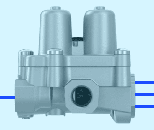
Four-circuit protection valve:
The four‑circuit protection valve is located between the air dryer and the air reservoirs. From inlet 1, the circuits are divided into four outlets: 21, 22, 23 and 24.
When a leak occurs in one of the circuits, the valve prevents all circuits from completely emptying. The remaining circuits will still operate, but at a lower pressure.
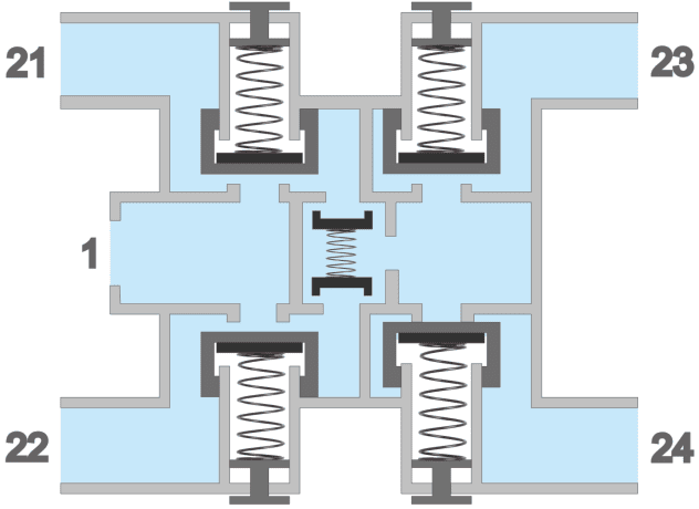
In the following images we see the drawing of the four‑circuit protection valve with the symbol and the codes.
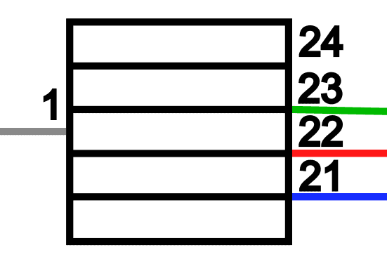
Legend:
1. Overflow valve circuit 1
2. Overflow valve circuit 2
3. Overflow valve circuit 3
4. Overflow valve circuit 4
5. Inlet
6. Check valves for circuit 3 and 4
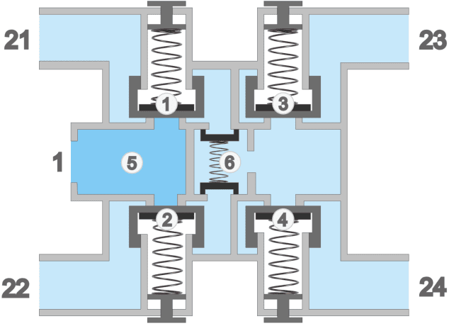
Connections 21 to 24: outlets circuit 1 to 4.
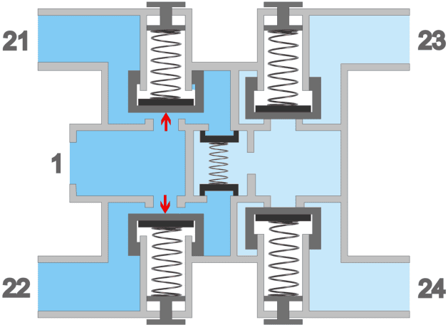
The four‑circuit protection valve contains four overflow valves (one for each circuit). The circuits for the service brake (1 and 2) are filled with air first. In the image below (1), the red arrows indicate the force that the air pressure exerts on the plate of the overflow valves, moving them against their spring force.
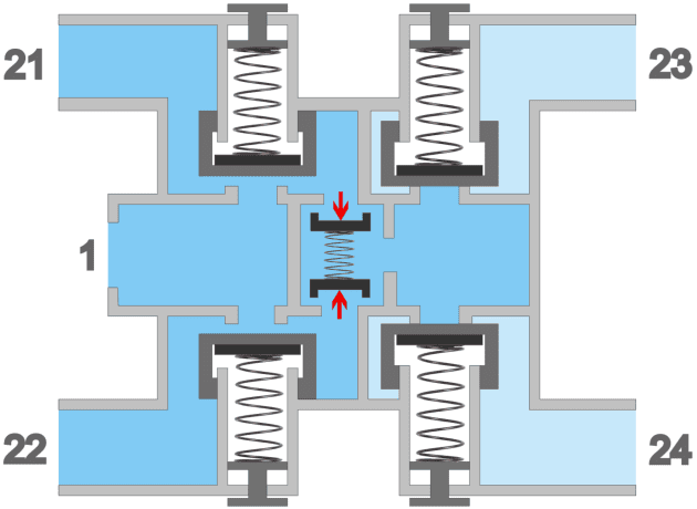
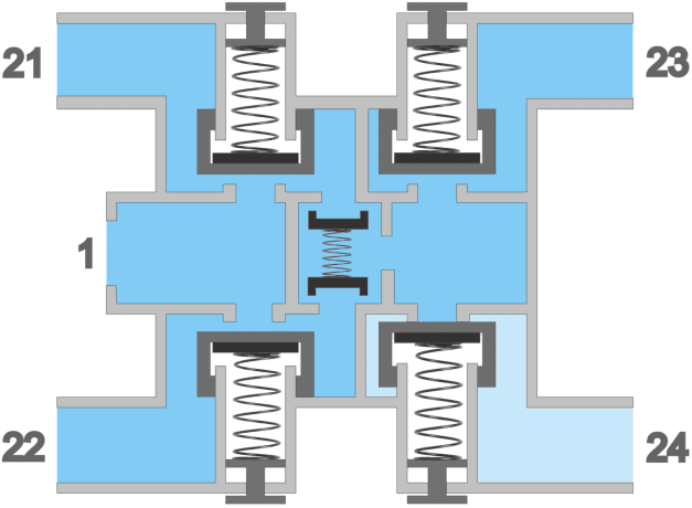
When a certain pressure is reached, the check valves of circuits 3 and 4 open, and the air enters the overflow valves of circuits 3 and 4. In image 2 we see that the air pressure moves the check valves inward against the spring force, allowing the air pressure to flow into the right-hand chamber.
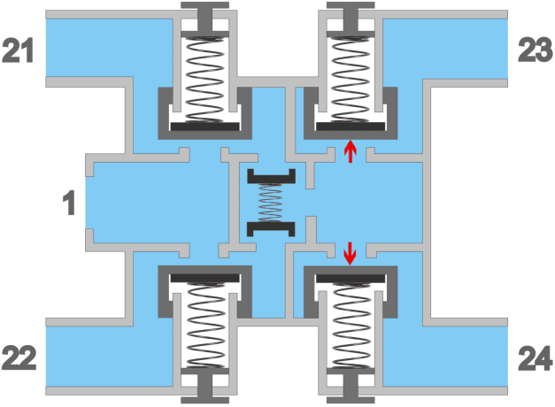
In the third image we see the force exerted on overflow valves 3 and 4. In this situation all four circuits are supplied with the same air pressure. This situation remains constant until the air pressure drops due to the engine being switched off, or in the event of a malfunction.
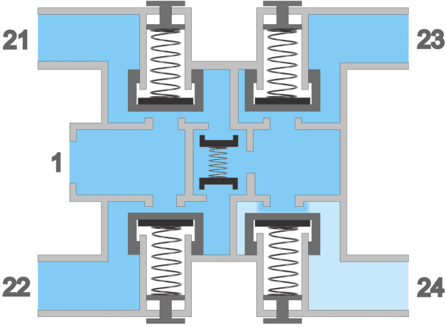
In the event of a leak in one of the circuits, the four-circuit protection valve protects against the other circuits draining. In the three images below you can see what happens if circuit 4 leaks. In image 4 we can see from the light blue color that the air pressure in circuit 4 is dropping. As a result of the pressure drop in circuit 4, this will initially affect the pressure in the remaining circuits. The overflow valve of circuit 4 closes (image 5), allowing the pressure in the other circuits to be restored. In image 6 we see that circuits 1, 2 and 3 are once again supplied with air pressure from the compressor, and that circuit 4 is isolated from the rest.
Air reservoirs:
During braking, the air pressure is used that is supplied from the air-supply side to the air-consumption side. After braking, the air pressure escapes to the outside air, and therefore cannot be used again. New air is needed to brake again. To brake several times in succession, a lot of air is needed, so it is important to store the required air in advance. Storage takes place in supply reservoirs, also called air reservoirs. Each circuit has its own reservoir. The reservoirs are located between the four-circuit protection valve and the foot brake valve, relay valve and check valve of the air-consumption side.
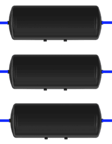
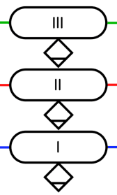
The illustrations show three reservoirs underneath each other, with next to them the symbols of the reservoirs and the water drain valves.
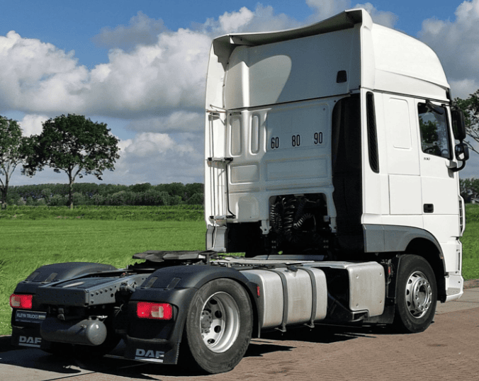
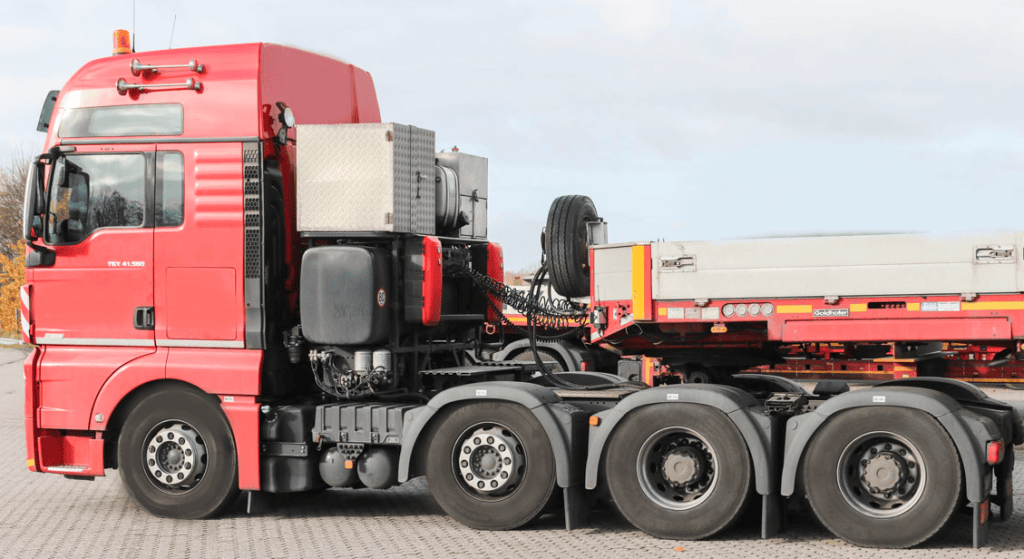
The images below show a DAF (left) with one of the air reservoirs at the rear of the chassis and a MAN (right) with two air reservoirs behind the front axle.
Related page: