Introduction:
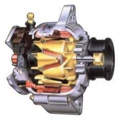
When the engine is running, the alternator (in Dutch called “dynamo”) ensures that the battery is charged and that the consumers are supplied with power (such as the radio, lighting, etc.). The alternator is driven by the multi-rib belt. The multi-rib belt drives the alternator pulley, which is connected to the internal shaft. The kinetic energy is converted into electrical energy (and heat) in the alternator.
The engine speed affects the alternator voltage. The faster the engine runs, the faster the pulley rotates, allowing more current to be generated. The voltage must not be too high and is therefore limited by the voltage regulator.
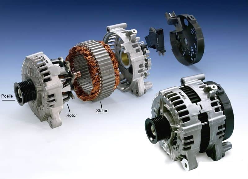
The image on the right shows an exploded view of an alternator. The pulley is mounted in the housing with a bearing. A shaft with the rotor is attached to the pulley, which starts to rotate as soon as the pulley is driven by the multi-rib belt. The stator is mounted between the two halves of the housing, and the rotor rotates inside it. On the back of the alternator there is usually a plastic cover, behind which the voltage regulator is located and where the alternator connections can be found.
AC voltage is generated in the alternator. In the vehicle’s electrical system DC voltage is used. The battery can only be charged with DC voltage as well. The AC voltage is converted into DC voltage by means of the diodes in the diode bridge. The magnitude of the generated voltage depends on:
- The speed at which the conductor and the magnetic field move relative to each other
- The length of the windings
- The strength of the magnetic field
On the housing (rear side) of the alternator, several terminals are marked with codes indicating what they are connected to:
- B+ goes to the battery; the charging voltage and charging current flow through this terminal.
- D+ is the control voltage for the rotor to regulate the alternator voltage.
- D- is the ground of the alternator.
- W is a terminal that used to be used for tachometers on older diesel engines. It is no longer used nowadays.
- DF or LIN are the possible terminals for the control of the rotor excitation from the engine management system.
Operation:
Current is generated because the rotor rotates inside the stator. The rotor is an electromagnet; it only becomes magnetic when current flows through it. The alternator therefore needs help from the battery before it can start charging. The residual magnetism in the alternator is not sufficient to allow an electric current to flow through the diodes.
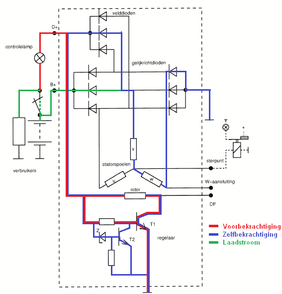
The current that magnetizes the rotor flows from the battery, via the ignition switch and the charge warning lamp to the D+ terminal of the alternator. The current then flows to the rotor. From the rotor the current flows via the regulator to ground. When the ignition switch is turned on, the charge warning lamp lights up and at the same time the alternator is magnetized. When the alternator starts charging, the charge warning lamp will go out.
When the alternator is charging, the north and south poles move relative to the stator. This induces an alternating voltage in the stator. During one revolution of the magnet, the voltage induced in the conductor has the shape of a sine wave, as shown in the illustration.
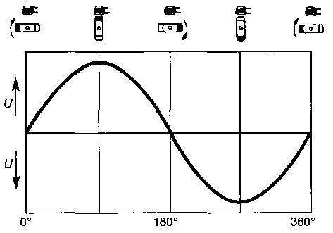
Because this is AC voltage and all consumers in the car operate only on DC voltage, rectification is still required. Diodes ensure that the AC voltage is converted into DC voltage.
The charging voltage and charging current must also be limited; when the engine is running at high speed and few consumers are switched on, the alternator only needs to charge a little. When more consumers are switched on, the alternator has to supply more charging current. At full load this can increase to 75 to 120 amperes (depending on the type of car). How all of this works is described in the chapters below.
Rotor:
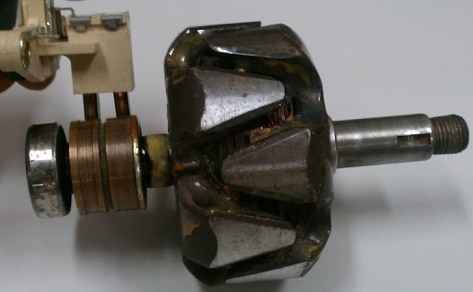
The rotor is not a permanent magnet, but an electromagnet. By allowing current to flow through the rotor, it becomes magnetic and an AC voltage can be generated. By increasing or decreasing the rotor current, the generated voltage can be controlled. This is the task of the voltage regulator.
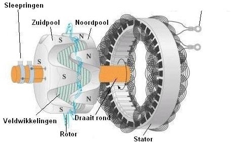
The rotor has claw poles (north and south poles). Each half with claw poles usually consists of 6 or 7 poles. The other half consists of the same number of poles, so there are 6 or 7 north poles and 6 or 7 south poles. We then speak of 12 or 14 pole pairs. The number of pole pairs affects the voltage generated in the stator.
The magnetic field in the alternator is created when the rotor is excited. This already happens when the car’s ignition is switched on. To excite the rotor, a field current is sent through the field windings. This current comes from the battery and is transferred to the field windings via the slip rings and the carbon brushes. It flows from the north pole to the south pole, because one slip ring is connected to the north pole and the other to the south pole.
When the rotor has been removed, it can be measured to check for faults. The rotor resistance is often around 3 ohms. Refer to the manufacturer’s data for the exact value.
Stator:
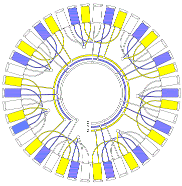
The alternator used in almost all cars is a three-phase alternator. This means that the alternator is made up of three stator coils connected to a single stator core and a rotor. Each stator coil produces its own generated AC voltage. Because all stator coils are mounted at an angle of 120 degrees relative to each other, the generated voltages are also shifted 120 degrees in phase. These voltages are rectified by the three negative and three positive diodes (a total of six diodes).
The stator core consists of stacked laminations, which are separated from each other by insulating material. The stator core strengthens the magnetic field in the alternator and thereby increases the generated voltage. The stator coils can be connected in two ways: by means of a delta connection (recognizable by 3×2 terminals) and a star connection (4 terminals, three of which are separate terminals and one terminal where the three ends of the coils are connected together). The star connection is the most common, because it allows a high voltage to be reached more quickly. The delta connection is used with alternators that have to deliver a lot of power.
If a stator coil makes contact with the stator core (short to ground) or if one of the coils is open (wire break), the stator will no longer work properly. A multimeter can be used to check whether there is a short to ground or a wire break. There is one condition: the stator coils must be disconnected; both ends must not make contact with other components. Often desoldering them is sufficient. The resistance of the coils must be very low; approximately 0.05 ohms. The resistance between the stator coils and the stator core must be infinitely high. If there is any resistance (even if it is extremely high), there is a connection.
Pre-excitation, self-excitation and charging current:
Pre-excitation:
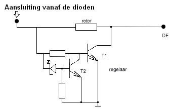
The engine is stationary and the warning lamp is on. The pre-excitation current flows via the battery, the ignition switch, the rotor and the regulator to ground. This is possible because in the voltage regulator the Zener diode is blocking and the base current of T1 is brought into conduction because T2 stops conducting.
Self-excitation:
When the engine has started, the rotor is magnetized sufficiently to switch over to self-excitation. The self-excitation current then flows via the rectifier diodes (negative side), the stator coil, the field diodes to the rotor, and via the voltage regulator to ground.
Charging current:
The stator coil generates an AC voltage because the rotor is rotating in it. The green line marks the path along which the current from stator coil V flows to the battery and consumers. The current is converted from AC to DC by a rectifier diode and flows via the B+ terminal to the battery and consumers.
The charging current that flows via the B+ terminal to the battery and consumers supplies the entire electrical system of the car. If the engine is off, the alternator does not supply any current and the consumers draw current from the battery. When the engine is running, the alternator must supply enough current to power all consumers. With the engine running, no current is drawn from the battery. The charging current of the alternator depends on the number of consumers switched on and the state of charge of the battery. The maximum charging current is usually stated on the alternator (often between 60 and 90 A).
The alternator charging voltage can easily be checked if there is any doubt about its operation. By measuring the positive and negative terminals of the battery with the engine running using a voltmeter (multimeter), you can check whether the alternator is charging properly:
- If the voltage with the engine running is around 14.2 volts, the alternator is working as it should;
- If the voltage is 13.8 volts, the battery is almost full and the consumers are switched off. The alternator then does not need to supply much voltage, which does not affect the charging voltage;
- If the voltage is 12.4 volts or lower, the alternator is not charging properly. This is also the voltage of a full battery, which indicates that there is a problem with the alternator;
- If the voltage is lower than 12.4 volts, the alternator is no longer charging and the battery will continue to discharge until the voltage reaches 8 volts. The engine will then stall and there will be no more electrical operation.
If the alternator no longer charges, you can choose to replace the alternator. This is often expensive, but it may be more economical to use a reconditioned alternator. Many reconditioning companies completely strip and repair the alternator, which often saves (more than) half the price of a new one. Always make sure to disconnect the negative terminal of the battery before replacing the alternator! If you do not do this and the B+ terminal comes into contact with the bodywork or the engine block, sparks can occur due to a short circuit, which can damage expensive electronic components.
Voltage regulator:
The voltage regulator controls the switching on and off of the magnetic field by switching the current through the rotor. The voltage regulator ensures that the charging voltage remains constant (between 13.2 and 14.6 volts). The charging voltage depends on the engine speed. The faster the crankshaft rotates, the faster the rotor will rotate. Without regulation, the voltage would rise to 30 volts at high speed, which is prevented by the voltage regulator. When the voltage exceeds the preset limit, the Zener diode (in the diagram) becomes conductive, causing the base of T1 to be led to ground by T2. T1 is blocked and the magnetic field collapses, which lowers the alternator voltage. As a result, the rotor current is interrupted, so that the alternator does not charge for a short time.
By continuously switching T1 on and off, the voltage is regulated.
If the voltage at the D+ terminal is lower than the set regulation voltage, current flows from D+ through the rotor to the D- terminal (ground), causing the alternator to generate voltage. If the voltage at D+ is higher than the regulation voltage, the Zener diode becomes conductive, causing transistor T2 to conduct. As a result, transistor T1 cannot conduct and no current flows through the rotor anymore. The magnetic field is switched off, so that the charging voltage drops. The voltage drops until the Zener voltage is no longer reached, after which transistor T2 is blocked and transistor T1 conducts again. This cycle is repeated continuously.
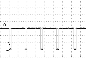
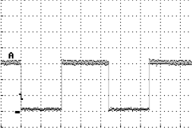
Below are two scope images that were measured at the DF terminal of the alternator. These signals are passed on to the engine control unit. The rotor is magnetized when it is switched to ground.
The signal in graph 1 was measured while few or no consumers were switched on. The rotor is therefore minimally magnetized. The duty cycle here is approximately 10%.
The signal in graph 2 was measured while many consumers were switched on. The rotor is much more excited here in order to achieve the 14.4 volt charging current. The duty cycle here is approximately 50%.
Rectifier diodes:
The alternator supplies AC voltage, but because only DC voltage is used in the car, the AC voltage must be converted to DC voltage. This is done by the rectifier diodes. Diodes allow current to flow in only one direction. The positive part of the alternating current is used, the negative part is lost.
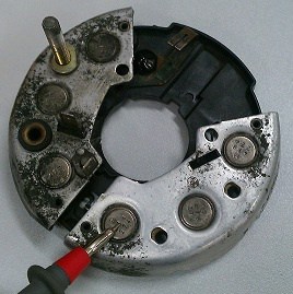
The image shows a disassembled diode bridge. The red test lead points to one of the three negative diodes. The positive diodes are on the other side of the diode bridge. The stud is the B+ terminal, where the thick cable going to the battery is mounted.
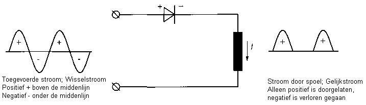
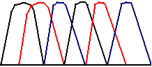
This is the principle of a single-phase alternator. In the image above (on the right-hand side) you can see that the phase is repeatedly interrupted: there is briefly no voltage, after which a new phase follows. In the section between the phases, no voltage is generated. To prevent this, star connections and delta connections are used in three-phase alternators. This produces the result shown below.
In the image below, three different colors can be seen: black, red and blue. These are the individual phases. The image shows that, between the black phases for example, there is a lot of space. By connecting the other phases in between, this space is bridged. This creates a smooth power supply.
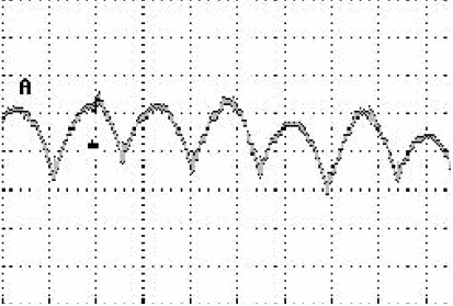
After rectifying the voltage with the rectifier diodes, a small ripple always remains. This is called the ripple voltage. This ripple voltage must never exceed 500 mV, otherwise malfunctions or defects in the vehicle electronics can occur. The image shows an oscilloscope pattern measured at the battery. When the engine speed changes, or when consumers are switched on, this pattern can change.
Overrunning pulley:
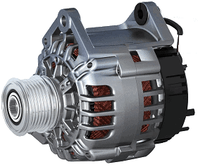
Nowadays, many alternators are fitted with an overrunning pulley (see image below). These pulleys can only be driven in one direction. When the multi-rib belt has been removed from the pulley and you turn the pulley by hand, you will notice that the internal mechanism of the alternator only turns in one direction and remains stationary in the other. This system protects the multi-rib belt. When the engine is running at high speed and the accelerator pedal is suddenly released, the engine speed will drop quickly. A heavy-duty alternator will decelerate less quickly. Its speed decreases more slowly than the engine speed. As a result, the multi-rib belt is subjected to a higher load and, in the worst case, can be cut in half, because the belt then has to brake the alternator. With an overrunning pulley, the alternator will follow during acceleration, but will spin down at its own speed during deceleration.
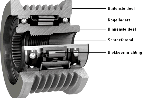
The pulley is mounted with a thread on the rotor shaft (see image above). The outer part of the pulley only drives the inner part in one direction of rotation. The locking mechanism ensures that the inner part is clamped against the outer part. The complete pulley is then locked so that the alternator is driven by the multi-rib belt. When the accelerator pedal is released, the inner part turns at a higher speed than the outer part; the engine speed has dropped faster than the speed of the rotor. The locking mechanism is then not active, allowing the ball bearings to enable the rotor to run at a different speed to the crankshaft.
The image shows an alternator that is equipped with an overrunning pulley.
Energy recuperation:
If the alternator is charging at its maximum capacity (with many consumers switched on), extra fuel consumption will occur. This is because the alternator will run under a higher load, as the magnetic field in the stator will then be stronger. The magnetic field causes the rotor to run under more load and the crankshaft has to pull harder on the multi-rib belt to keep it turning. Nowadays, car manufacturers have found a clever solution for this. The alternator always charges, but while driving it will not simply charge at its maximum capacity (unless the battery is really empty). Maximum charging takes place when the car is in overrun on the engine. That is, when the driver lifts their foot off the accelerator pedal and lets the car coast (for example when approaching a traffic light or on a motorway exit). At such a moment, the car does not use any fuel anyway and the kinetic energy (energy of motion) of the vehicle keeps it rolling. The battery is now charged at maximum capacity until the accelerator is pressed again. At that moment, the alternator ensures that the power supply remains stable. This method of charging results in lower fuel consumption.
Possible alternator faults:
A number of typical problems or faults can occur in the alternator. Often the technician will then know what he or she can check or measure next. Below are some characteristic complaints:
- The charge warning lamp illuminates normally during pre-excitation, but only goes out at a higher engine speed; fault in the alternator (probably a defective field diode).
- The same complaint as above, except that it also glows dimly with the engine running at high speed or with many consumers switched on; fault in the alternator (probably a defective diode).
- The charge warning lamp glows dimly during pre-excitation, but only goes out at a higher engine speed; probably a fault in the alternator or a fault in the wiring or its connections.
- The charge warning lamp does not come on during pre-excitation, nor with the engine running; defective alternator, poor wiring/connections or a defective charge warning lamp.
Checking the charging voltage and current:
The amount of energy supplied by the alternator depends on its capacity and on the demand from the consumers and the battery. The alternator must for example be able to supply 100 A in order to power the consumers and charge an empty battery at the same time. When the battery is full and no consumers are switched on, the alternator’s energy production drops to almost zero. The maximum capacity of the alternator is often stated on the type plate and is usually between 65 A and 120 A, for example 14V 17/85A (regulated voltage 14V, charging current of 17A at 1800 rpm and 85A at 6000 rpm).
If there is a fault in the alternator or wiring, the maximum capacity under load cannot be reached. This can be checked by measuring the charging current with a current clamp while the alternator is under maximum load, for example by switching on as many consumers as possible. The measured value must correspond to the value stated on the alternator.
The regulated voltage can be measured between the B+ terminal and ground at an engine speed of 2000 rpm. The voltage must be between 13.8 V and 14.5 V. To check the wiring, measure the voltage difference between the positive terminal of the battery and the B+ terminal of the alternator; this must be lower than 0.4 V. If the voltage is higher, there is a problem with the wire or the connections. A poor ground circuit can affect both the charging system and other systems. This can be checked by running the engine at 2000 rpm and measuring the voltage between the negative terminal of the battery and the alternator housing; this voltage must also be lower than 0.4 V.
Related page: