Introduction auxiliary brake – parking brake:
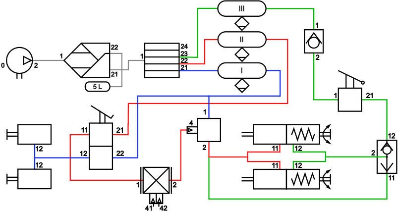
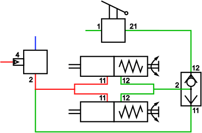
With the auxiliary brake / parking brake lever it is possible to brake proportionally on the rear brakes, and the parking position is activated. This section falls under the “air-consuming” section, of which the components are indicated in green in the image below.
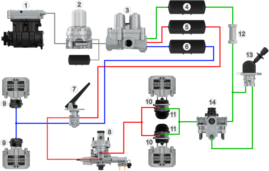
Legend auxiliary brake / parking brake:
1 to 6: Air supply
12: Check valve
13: Parking brake valve
14: Relay valve
- Blue: air supply
- Yellow: air-consuming
- Green: parking brake / emergency brake
In the four-circuit protection valve (3) the brake circuits are separated from each other. In the image above we see the brake circuits indicated with colours:
- circuit 1 (red) is the brake circuit of the rear wheels;
- circuit 2 (blue) is the brake circuit of the front wheels;
- circuit 3 (green) is the brake circuit of the auxiliary brake or parking brake;
- circuit 4 is the brake circuit of the trailer or semi-trailer (not shown).
The auxiliary and parking brake are separated from the other air-consuming circuits in the four-circuit protection valve. Air tank 4 serves as air storage.
From the air tank, the air flows through the check valve (12), which only allows the air to pass in one direction. Air flow in the opposite direction is blocked. The check valve is connected to the inlet of the parking brake valve (13).
The driver operates the lever of the parking brake valve. The lever is usually mounted in the dashboard or next to the driver’s seat. With the travel of this lever it is possible to brake, and when the end stop is reached (to park) all air has disappeared from the spring brake cylinders (11), causing the brakes to be locked. The parking brake valve controls the relay valve (14), which – based on the amount of air from the parking brake valve – allows the air pressure from the check valve to pass to the spring brake cylinders (11). In addition to the relay valve we sometimes also find the anti-compounding valve, also called the two-way valve. In the paragraph “anti-compounding valve” this valve is explained, so it is not yet included in this diagram.
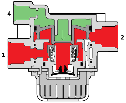
Check valve:
Without air pressure the spring brake cylinders remain in rest position, causing the brake linings to be pressed against the brake disc or brake drum. Air pressure is required to operate the spring brake cylinders and to release the truck’s brakes. If a leakage occurs in one of the other brake circuits and a pressure drop occurs in circuit 3, there is a chance that the rear brakes will start dragging.
The check valve prevents air from flowing back to the tank. In the flow direction (from 1 to 2) the ball is pushed off its seat by the air pressure, but in the opposite direction (from 2 to 1) the ball blocks the air flow.
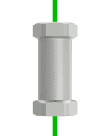
In older trucks the check valve was often a separate component, but in more modern trucks it is often built into another component, such as the four-circuit protection valve or the parking brake valve.
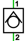
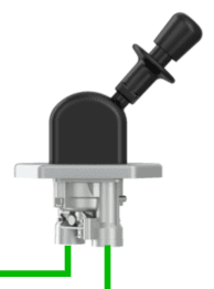
Parking brake valve:
With the parking brake valve (also known as the emergency brake or hand brake valve) the driver can vent and supply air to the spring brake cylinders of the rear brakes.
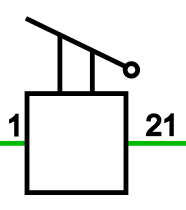
The following two images show a drawing of the parking brake lever on the valve, with the symbol next to it. The codes indicate the inlet and outlet of the valve: 1 is the inlet and 21 is outlet 1. This valve can also have an outlet 2, which is indicated with 22.
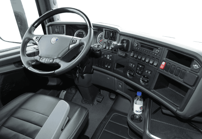
In the following image we see the dashboard of a Scania R730 (2010) with the parking brake lever next to the steering wheel, in the dashboard.
- Vented: without air pressure the brakes are locked (parking position);
- Supplied with air: the rear brakes are released (driving position);
- Partially supplied with air: while moving the lever towards the parking position, the pressure in the spring brake cylinders drops and braking will occur. The further the lever is moved towards this position, the harder the braking.
In the current position it is on the parking brake. To release the parking brake, the lever must be pulled towards you to tilt it upwards.
When the lever is pointing upwards, the spring brake cylinders are supplied with air and the vehicle can be driven.
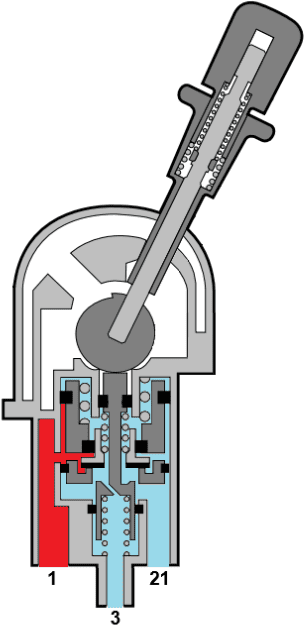
In the following image we see the mechanism in the parking brake valve with the legend next to it.
The driver operates the handle (1) by pulling the release button outwards against the spring force. This releases the lock, and the lever – and with it the eccentric (2) – can be rotated about its axis.
The eccentric has an off-centre shaft, so when the lever is rotated, the push rod (3) is pressed downwards against the spring force.
The sealing valve (4) and the underside of the push rod (5) provide the blocking or air passage during the different positions. In the state shown, sealing valve 4 blocks the passage of air between inlet (code 1) and outlet (21). When the truck is put on the parking brake, the air from connection 21 escapes via the vent connection (code 3) to the atmosphere.
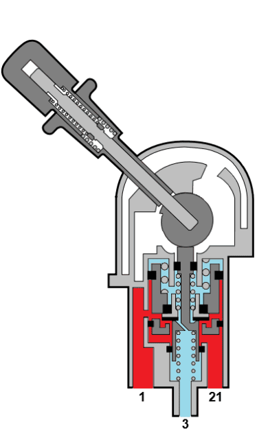
In the images below the air flow is shown in the positions “driving” and “parking”.
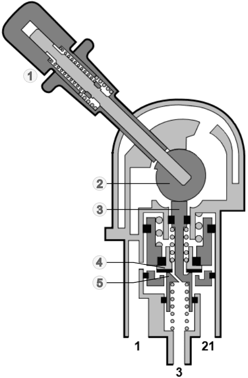
Legend:
1. Handle with spring
2. Eccentric
3. Push rod
4. Sealing valve
5. Underside push rod
- Driving position: inlet 1 and 21 are interconnected, so that the air supply from the air tank reaches the spring brake cylinders. The spring brake cylinders are operated by the air pressure, releasing the brakes;
- Parking position: the air to the spring brake cylinders has been vented via vent 3 and the supply via inlet 1 is closed. The spring brake cylinders are vented, causing the brake segments to be pressed against the disc or drum.
Relay valve:
A relay valve is mainly used to enable a fast response time (supply and venting) of the brake cylinders over a large distance. A long, thin air line runs from the cab to the rear axle to control the relay valve. The air pressure from the tanks is already present there and can be allowed through or blocked by the control line. The operation of the relay valve is similar to a relay in electronics: with a small control current a large main current can be switched on and off. However, in contrast to the electrical relay, the control pressure determines the degree of air flow from the tank to the brake cylinder.
In several places in the air brake system a relay valve may be located:
– between the ALR and the diaphragm cylinders of the rear brakes;
– between the parking brake valve and the spring brake cylinders of the rear brakes.
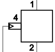
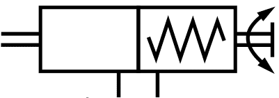
The relay valve has the following connections:
- 1 and 2: inlet and outlet
- 4: control.
The air pressure at connection 4 (control) determines the level of air pressure at connection 2 (outlet). The higher the control pressure, the higher the outlet pressure.
The images below show the relay valve in the de-energized and energized states. The level of control pressure determines the position of the plunger that is pushed down. The further the plunger is pushed down, the larger the opening between 1 and 2 will be.
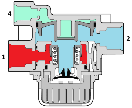
Legend:
1. inlet (supply air)
2. outlet
4. control
- Green: control pressure
- Red: pressure from reservoir
- Blue: atmospheric pressure
Anti-compounding valve:
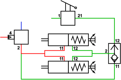
In an air brake system a so‑called anti-compounding valve, or in other words: a two-way valve, can be used. This valve is located between the inlet of the spring brake cylinders (12) and the outlets of the parking brake valve (21) and relay valve (2). In the diagram below this valve is shown in place of the relay valve.
The purpose of the anti-compounding valve is to prevent excessively large forces acting on the brake when the service brake and parking brake are operated at the same time.
Driving mode:
The parking brake is released and no braking is taking place. Connection 12 is controlled with full air pressure via the parking brake valve. The plunger in the valve is pushed down so that connection 11 is shut off and there is a passage via outlet 2 to the spring brake cylinder. The spring in the spring brake cylinder is compressed, which deactivates the parking brake.
When braking, the foot brake valve directs the air via the relay valve to the diaphragm cylinders (11) so that the service brakes are applied. The air from the foot brake valve is also present at connection 11 of the anti-compounding valve. With partial braking, the pressure at connection 11 is lower than the pressure at 12, causing the plunger to keep connection 11 closed.
Parking brake mode:
When the truck is parked, the green lines in the illustration are without pressure. The spring in the spring brake cylinder presses the brake linings against the brake drum or brake disc to keep the truck stationary. The plunger is in the middle position.
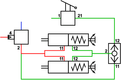
Parking brake and service brake mode:
The parking brake valve has vented connection 12 of the anti-compounding valve. The spring in the spring brake cylinder presses the linings against the disc or drum with full force.
When the driver brakes while parked, the foot brake valve – via the relay valve – supplies connection 11 of the anti-compounding valve. The plunger in the valve is pushed upward by the air pressure so that connection 12 is shut off. Via connection 2 the spring brake cylinders are pressurized to compress the spring. This prevents the force on the brake system from becoming too great and causing damage.
Combined diaphragm and spring brake cylinder:
A diaphragm cylinder is a type of brake cylinder. The energy delivered by the supplied air pressure is converted into movement in the diaphragm cylinder. By means of a lever this movement is converted into a force that presses the brake lining against the brake disc or brake drum.
The force with which the brake lining is pressed on is partly dependent on the lever ratio and the air pressure in the diaphragm cylinder. The diaphragm cylinder is used in the service brake. The diaphragm cylinder is not suitable for parking, because with the engine switched off in the parking position there is (assuming the reservoirs are no longer filled) no air pressure available to press the brake linings against the disc or drum. That is why trucks are fitted with a spring brake cylinder for the parking brake, which is often combined with the diaphragm cylinder for the service brake.
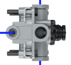
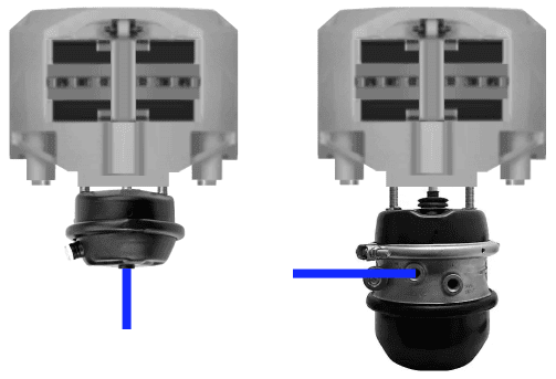
In the illustration alongside we see two brake calipers with two types of brake cylinders underneath:
- left: diaphragm cylinder of the front axle.
- right: diaphragm cylinder with the spring brake cylinder of the rear axle underneath.
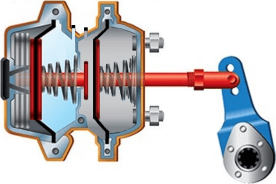
The illustration below shows a combined diaphragm and spring brake cylinder. Number 1 indicates the air connections with which the air chambers A (parking brake) and B (service brake) are pressurized and vented.
- Left section: here are the components of the emergency and parking brake. The powerful spring (3) pushes the diaphragm (2) and the red rod (6) to the right, putting the lever in the “parking” position. At rest the spring, via the mechanism, presses the brake linings against the brake disc or brake drum;
- Right section: the diaphragm (4) and the spring (5) are pushed into the far-right position in the parked state to allow the push rod to make the outward movement.
In the parked state there is no air pressure present in chambers A and B. Atmospheric pressure prevails here.
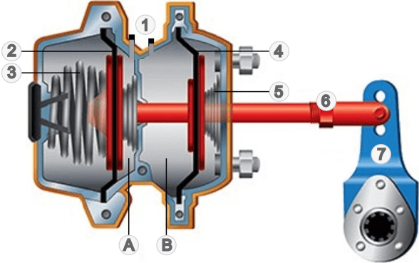
Legend:
1. Air connections spring brake (left), diaphragm (right);
2. Diaphragm parking brake
3. Powerful spring parking brake
4. Diaphragm service brake
5. Spring service brake
6. Push rod
7. Lever
A. Air chamber to release parking brake
B. Air chamber to operate service brake
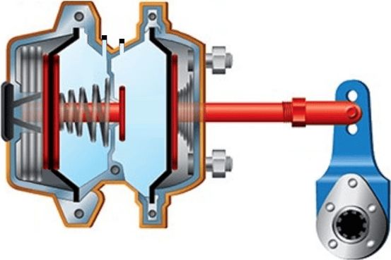
Releasing the parking brake:
To release the parking brake, the driver moves the parking brake valve to the driving position. The parking brake valve directs air pressure of approximately 5.5 bar to the spring brake chamber. Air chamber A is filled.
In the illustration we see that air chamber A is coloured light blue. Because the spring of the parking brake is compressed, the spring of the service brake pushes the push rod to the left. The lever then tilts in the direction that releases the brake linings from the disc or drum.
In this position the spring brake chamber is pressurised, the brake is released and the wheel can roll.
Operating the service brake:
While driving, the chamber of the spring brake unit remains pressurised. To brake in a controlled way, the driver operates the foot brake valve, which admits air pressure to the right-hand chamber. This pushes the diaphragm to the right against the spring force, while the push rod also moves to the right. In this position, as shown, maximum braking is applied.
Operating the parking brake:
The driver operates the parking brake lever to return the spring brake unit to the parking position. When the truck is stationary, the lever can be moved into this position in one smooth motion. In the event of a failure in the service brake, the driver can gradually move the parking brake lever while driving to apply more or less pressure with the spring brake chamber.
When the parking brake lever is moved to the “park” position, this releases the air pressure from the left air chamber. The spring pushes the push rod fully to the right, pressing the brake linings firmly against the discs or drums.
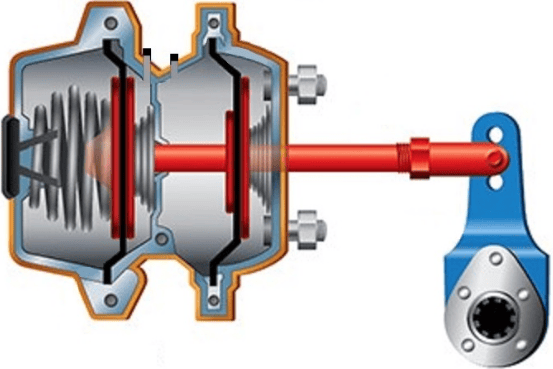
Without air pressure, the parking brake basically cannot be released. To still be able to let the wheel roll, there is a spindle at the rear of the spring brake unit. Using tools (ratchet with a socket), the spindle can be turned to manually relax the spring.
Related page: