Introduction:
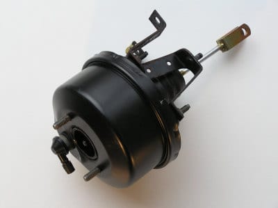
Vacuum brake boosters are used on almost all passenger cars. With the aid of the brake booster, the driver does not need to press the brake pedal as hard to achieve the same braking effect as with a car without a brake booster. A brake booster helps move the pistons in the master brake cylinder. The brake booster is located in the engine compartment and is connected to the brake pedal by a pushrod (see the right-hand pushrod in the image). The master cylinder is mounted directly on the brake booster (left side of the image). The force exerted on the brake pedal is amplified by approximately 3 to 4 times.
Operation of the vacuum brake booster:
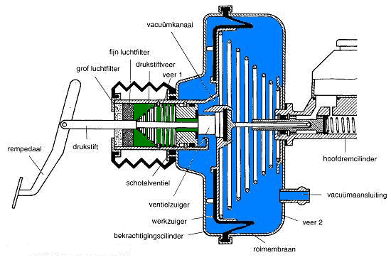
Rest position:
The engine is running, but the brakes are not being applied. There is a vacuum in both the left and right side of the booster cylinder. There is a vacuum in the blue-coloured areas. Through the vacuum connection, air is drawn out of the booster. This happens via a connection to the intake manifold or via a separate vacuum pump. The outside air pressure (green) is shut off from the booster. The spring pushes the working piston as far as possible to the left.
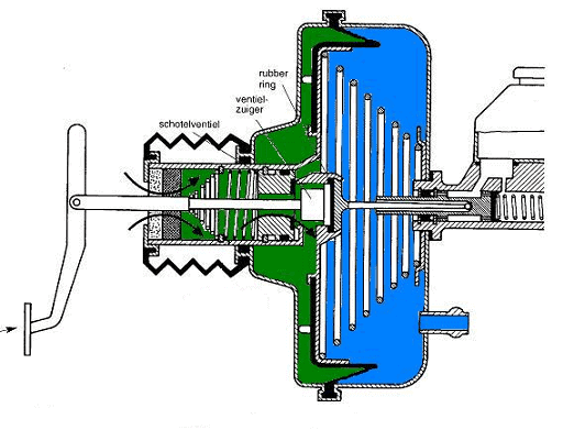
Beginning to brake:
When the brake pedal is pressed, the control piston moves to the right. It comes away from the disc valve, causing the left side of the booster cylinder to be partially filled with outside air pressure (green). The vacuum (blue) disappears. To the left of the working piston there is now a pressure that is lower than the outside air pressure, but higher than the vacuum. The boosting is therefore not yet at its maximum at this moment.
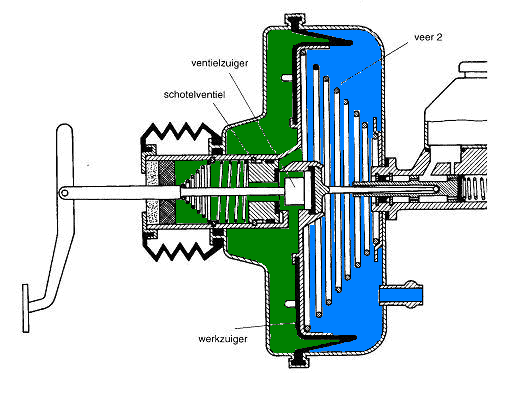
Maximum boosting:
The brake pedal is pressed further. The connection between the control piston and the disc valve remains open, allowing the left side to be filled with more outside air pressure. On the left side of the booster there is now the maximum outside air pressure and on the right side a maximum vacuum. When the brake pedal is pressed to the maximum, the spring in the brake booster is also compressed. This provides the maximum braking force.
When the brake pedal is released, the spring in the brake booster pushes the working piston back to the left. The control piston will again rest against the disc valve, freeing the vacuum opening. The outside air pressure disappears again from the left side of the booster cylinder and a vacuum is created again. The brake booster is now back in the rest position. The situation as shown in image 1 now applies again.
Vacuum connection and pump of the vacuum brake booster:
The required vacuum for a vacuum brake booster is often obtained from the engine vacuum in a petrol engine. A hose runs from the brake booster to the intake manifold. Because there is a vacuum in the intake manifold, vacuum is also drawn from the booster. If the engine is switched off and the brake pedal is pumped several times, the pedal will feel hard. That is because all vacuum has disappeared from the brake booster. When the engine is then started again, the pedal will drop and can be pressed further. This must therefore always be taken into account when a vehicle is being towed; in the car where the engine is not running, 3 to 4 times as much force will have to be applied to the pedal. The power steering will also not work. It is therefore wise to drive calmly.
It can happen that the pedal feels hard immediately after switching off the engine; it seems as if the vacuum disappears immediately. This can be caused by a split vacuum hose between the brake booster and the engine, or by a defective check valve in the hose. This is usually a round piece of plastic between two sections of the hose.
If the hose in question is split, it must be replaced as soon as possible. If it splits further or breaks, the entire brake boosting will fail.
There are two different types of vacuum pumps, namely the vane pump and the diaphragm pump. The vane pump is also called the tandem pump or the vacuum pump. The operation and application of these pumps is described on the vacuum pump page.
Hydraulic brake booster:
Hydraulic brake boosters are rarely used in passenger cars. Therefore, this page will not go too deeply into them. With hydraulic brake boosters, the force exerted on the master cylinder is supported by fluid pressure. The hydraulic brake booster is placed between the brake pedal and the master cylinder.
In some systems, the brake boosting system (by means of the accumulator) is combined with the power steering. In the image below, you can see from the colours which lines belong to which components. Hydraulic oil or ATF (Automatic Transmission Fluid) is used in all visible lines. In the system with the master cylinder and brake lines to the calipers/drums, normal brake fluid is used. The fluid of the brake booster and that of the master cylinder are therefore different and must of course not be mixed.
Components of the hydraulic brake boosting system:
- Hydraulic brake booster: The supplied oil in this brake booster will assist the pedal force.
- Master cylinder: This is where the brake fluid pressure build-up starts.
- Pump: The pump (driven by belt or electric motor) provides the required pressure. In these types of systems, the same pump is often also used for multiple systems, such as power steering, ride height control, hydropneumatic suspension, etc. Other systems use a separate pump.
- Reservoir: The reservoir stores the hydraulic oil or ATF.
- Accumulator: In the accumulator, the oil is stored under a high pressure of 36 to 57 bar.
- Flow control valve: This ensures that the accumulator remains filled and controls the flow of fluid for the brake booster and power steering.