Introduction:
Capacitors are used in electrical equipment such as circuit boards in computers, televisions and radios, but on this page we apply the concept of the “capacitor” to automotive technology. In automotive technology, capacitors can be found in, among other things, electronic filters, control units, level gauges, ignition coils and relays.
A capacitor stores energy. This energy can be used in a radio filter for interference suppression (the capacitor filters out certain frequencies, such as alternator noise), or for the interior lighting as a switch-off delay. When the door is closed, the interior light will then slowly go out. Voltage fluctuations from rectifiers (diodes) are also smoothed out with it. The capacitor can charge and discharge in a short time.
Operation of the capacitor:
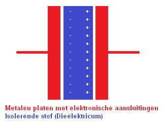
A capacitor consists of two (usually metal) conductors separated by the dielectric. That is a non-conductive material such as plastic, or otherwise by a vacuum.
When an electrical voltage source is applied to the plates, both plates will be charged. The left plate (with -) will be charged negatively and the right plate (with +) positively.
The charging current stops as soon as the voltage difference between the two plates is equal to the voltage difference of the voltage source. This charging takes time. This time can be calculated. This will be discussed later on this page.
The charging current stops as soon as the voltage difference between the two plates is equal to the voltage difference of the voltage source. This charging takes time. This time can be calculated. This will be discussed later on this page.
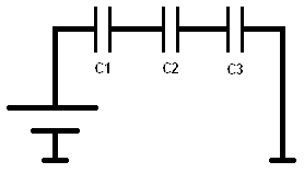
Series circuit with capacitors:
With capacitors connected in series, the charge on all capacitors is the same.
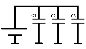
Parallel circuit with capacitors:
With capacitors connected in parallel, the voltage across all capacitors is the same.
Capacitive level sensor:
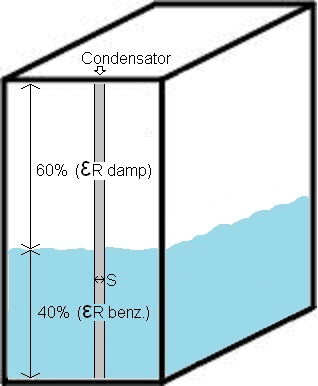
This example deals with the level sensor in a car’s fuel tank. There is a shared dielectric.
The principle of capacitive level measurement is based on the change in the capacitance of the capacitor, which depends on the change in level (in this case the fuel quantity).
Petrol is not a conductive substance, so no short circuit can occur between the plates of the capacitor due to conduction, as would be the case with, for example, water.
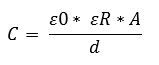
The capacitance of the capacitor can be determined using a formula. The meanings of the symbols are as follows:
- C = capacitance
- A = plate surface area
- d = distance between the plates
The illustration shows that the tank is filled to 40% with petrol. The remaining 60% is vapour. The grey bar is the capacitive capacitor with distance S (between the plates). With the general formula, the capacitance, and therefore the tank level, can be determined.
Data:
Dielectric constants:
ε0 (vacuum) = 8.85 x 10⁻¹² (power to the minus twelfth)
εR petrol = 2.0
εR vapour = 1.18
The surface area (A) of this capacitor is 200mm² (length x width). The distance between the electrodes (S) is 1.2mm.
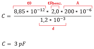
Because the tank is 100% full, we assume that the dielectric constant of petrol (2.0) acts over the total surface area of the capacitor (200mm²). When the tank is no longer 100% full, but 40% (as in the illustration above), the total surface area of the capacitor must be divided into percentages (40% and 60% to make 100 together). The 40% is for petrol, and 60% for the vapour. Therefore, two formulas must be made (C1 and C2):
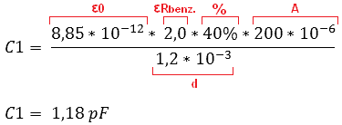
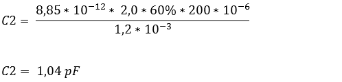
The formulas show that with 40% petrol the capacitor is charged to 1.18 pF and with vapour to 1.04 pF. Because the 40% and the 60% must be added together to make 100%, the capacitance values must also be added.
That can be done as follows: 1.18 + 1.04 makes 2.22 pF.
This 2.22 pF is passed on to the fuel gauge on the dashboard and, among others, the ECU.
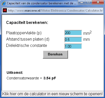
Calculator:
Instead of filling in the formula yourself every time, the data can also be entered into the calculator. It will then automatically calculate the capacitance of the capacitor. Also very useful for checking the calculated answer!
Click on the image below to start the calculator. It will open in a new window:
Charging and discharging time of the capacitor (RC time):
First, the concept of Tau will be explained:
As soon as a capacitor is placed in series with a resistor, the capacitor will be charged until the applied voltage (the source voltage, i.e. the battery voltage) is reached. It has been established that the capacitor is charged to 63.2% of the applied voltage after 1 (Tau). At 5 the capacitor is 99.3% charged. (Theoretically, the capacitor will never be fully 100% charged). The following illustration clarifies this:
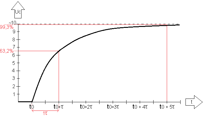
The charging of the capacitor is shown in the graph above. At t0 the capacitor is switched on, and at t0 + 5 it is charged.
At the time t0+ (on the x-axis) the capacitor is exactly 1 charged, because it was switched on at time t0. On the y-axis it can be seen that this is at 63.2% of Uc. At time t0+5 the capacitor is 99.3% charged.
With the formula = R x C the amount (Tau) is calculated.
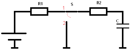
In the circuit below there are two resistors in series with each other. The total resistance is therefore R1+R2. That makes 10+10=20k. (20×10^3). Multiplied by C of 10 microfarad (10×10^-6) makes (200×10^-3) = 0.2.
This 0.2 must be entered into the calculation in a moment.
R1 = 10k
R2 = 10k
C = 10µ
Both the resistance values and the capacitance of the capacitor determine the charging and discharging time of the capacitor. The speed at which the capacitor must charge and discharge can be very important. Especially in circuits in microprocessors this time must be very short. For the switch-off delay of the interior lighting of the car, the time may be quite long. The general formula for the switching times is as follows:
Uct stands for the voltage at a certain time. This time is calculated in the formula. Uct 0 is the initial voltage, where the charging or discharging starts. Uct ~ (symbol for infinity) stands for the voltage that it can become at most (that is the applied voltage / battery voltage). The e stands for the e power. This is a natural logarithm. It is an exponential number. The -(t1 – t0) divided by τ (Tau) is now in exponent form. So it must also be pronounced and calculated as e to the power of -(t1 – t0) divided by τ.
Then follows + Uct ~. This is again the applied voltage / battery voltage.
Once this calculation has been carried out, the result is in volts (voltage).
The next paragraph contains an example with a circuit:
Charging the capacitor (with known charging time):
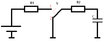
In the diagram the switch is closed. A current flows from the battery via the resistors to the capacitor. We want to calculate the voltage when the capacitor has been charging for 200 milliseconds (200 x 10^-3).
U = 10 V
R1 = 10k
R2 = 10k
C = 10 µF (microfarad).
τ = R x C
τ = (10,000 + 10,000) x 0.000010 = 0.2
τ = 200 x 10^-3
In formula form, this becomes:
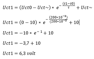
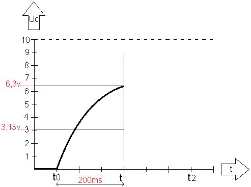
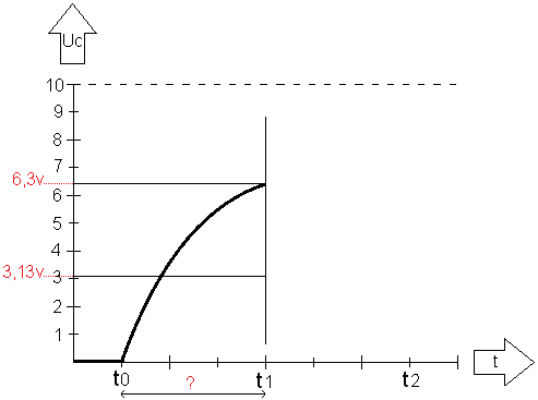
From t0 to t1 the capacitor is charged to 6.3 volts. This is equal to 1τ (because at 1 the capacitor is charged to 63.2%). The graph based on the calculation then looks as follows:
Discharging the capacitor:
Now we are going to discharge the capacitor. In the diagram the switch is moved from position 1 to position 2. The power source (the battery) is disconnected from the capacitor circuit. In the diagram, both sides of the capacitor are connected to ground (via resistor R2). The capacitor will now discharge. Again, the resistance value and the capacitance of the capacitor determine the discharge time, just as they did for the charging time. However, there is now one resistor less (because R1 is no longer in the same circuit). Therefore, the discharge time will now be shorter than the charging time:
Now we fill in the formula again to calculate Tau:
τ = R x C
τ = 100,000 x 0.001
τ = 100
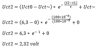
According to the formula, after 100 ms the capacitor has discharged to 2.32 volts. If we did not measure t1–t2 over 100 ms but over 200 ms, then the graph would again almost reach 0 volts. Charging does take more time than discharging, because during discharging there is 1 resistor in the circuit, whereas during charging there are 2 resistors connected in series. So in principle, the capacitor will need more than 200 ms to reach 0 volts. If the switch is flipped back to position 1 at t2, the capacitor would immediately start charging again.
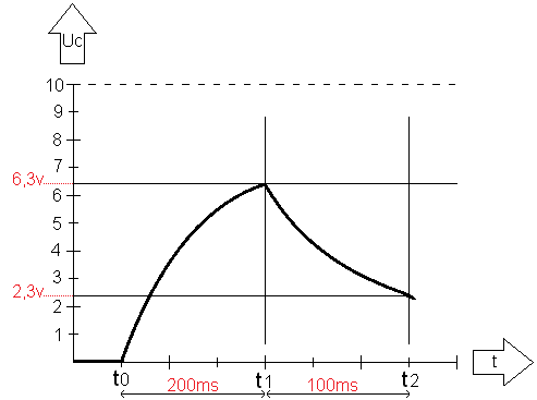
We can then plot the discharge period in the graph:
Charging the capacitor (with known final voltage):
When charging the capacitor in the example above, the charging time (200 ms) was known. Using the data for initial and final voltage, the charging time, and the number of Tau, the final voltage could be calculated. The capacitor was then charged to 6.3 volts after 200 ms.
Now we come to the situation where the charging time is unknown, but the final voltage is given. For convenience we use the same example;
(The resistor values and the type of capacitor are the same as in the first example).
R1 = 10k
R2 = 10k
C = 10µF (microfarad).
τ = R x C
τ = (10,000 + 10,000) x 0.000010 = 0.2
τ = 200 x 10^-3
What we now want to know is: how much time does it take (from t0 to t1) to charge the capacitor to 6.3 volts?
By filling in the known values in the first‑order differential equation, we cannot immediately obtain an answer. The formula has to be rearranged, because −(t1 − t0) is unknown and that is what we essentially want to find.
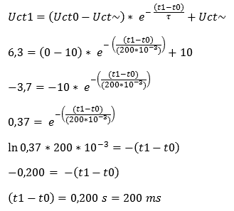
Explanation: First the basic formula is written down. We fill this in with the data that are known. Because we want to know the time for a charge level of 6.3 volts, we enter this at the beginning of the formula. The (t1 − t0) remains written as is.
Next, we divide the Uct~ of 10 V by the 6.3 V on the left side of the formula, which yields an answer of 3.7 V. The +10 can now be crossed out.
The next step is to eliminate the −10 (the number in front of the exponential). By dividing −3.7 by −10, this term is removed. On the left side of the formula we now enter 0.37.
Now it is time to eliminate the exponential. The inverse of an exponential is ln, the natural logarithm (just as the inverse of a power is the root).
By entering the formula into the calculator using the ln button, the result −0.200 is obtained. Because both sides of the = sign are negative, the minus signs can be crossed out.
This yields 200 ms as the answer. So it takes the capacitor 200 ms to charge to 6.3 volts. That is correct, because in the first calculation of the charging time this was a given which was used to calculate the 6.3 volts.
With this formula, the time at e.g. 3 volts can also be calculated. Then change the 6.3 volts to 3 volts, subtract 10 volts from it, divide this by −10 volts, multiply this again by the ln and by 200 · 10^-3. This gives an answer of 71 ms.