Check valve:
A check valve allows fluid flow to pass unhindered in one direction and blocks the fluid flow in the opposite direction.
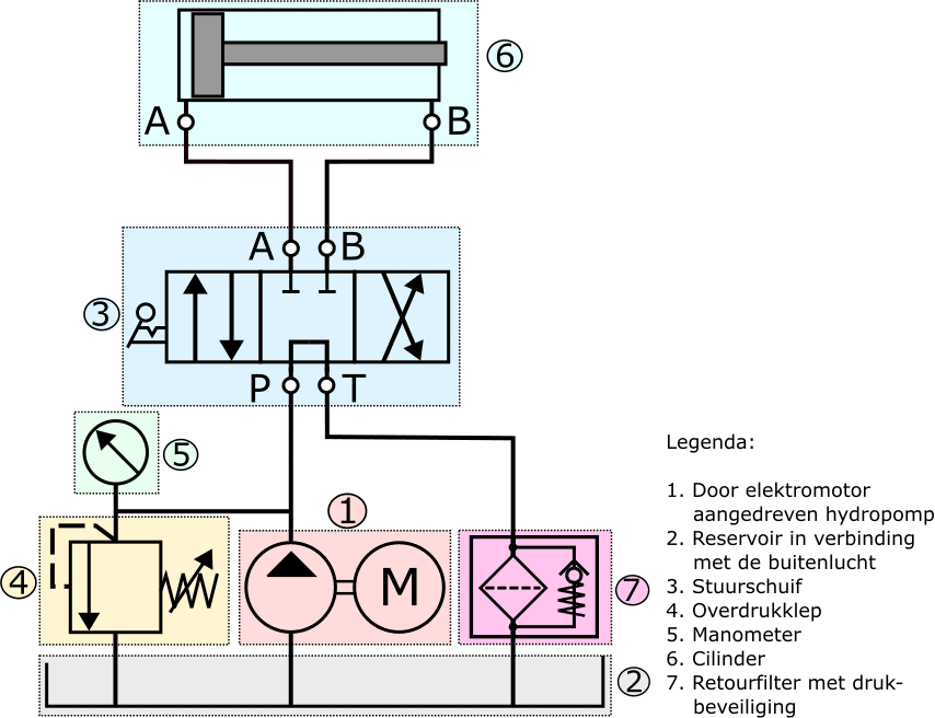
The check valve in the following diagram is located in the housing of the return oil filter. At rest, the spring presses the ball valve onto its seat. When the fluid pressure above the ball valve becomes high enough to overcome the spring force, the ball valve opens and the fluid can flow past the check valve to the reservoir. Here the check valve serves as protection against excessive pressure, which can arise when the filter element is so contaminated that the fluid flow becomes obstructed.
We also find the check valve as a safety component in hydraulic systems of, for example, a tipper truck. The valve is mounted in the hydraulic cylinder and prevents the load bed from dropping uncontrollably in the event of a sudden hose failure. Instead, the ball immediately shuts off the volume flow as a result of the surge pressure, so that the loaded cylinder comes to an immediate standstill.
We find the check valve not only in safety systems, but also in circuits where we want the hydraulic oil to flow through a component in only one direction. An example of this can be seen in the following image.
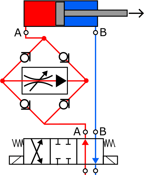
Between the directional control valve and the cylinder supply we see a flow control valve in a Graetz circuit. This circuit makes it possible for the fluid to flow through the flow control valve in the direction of the arrow, regardless of how the cylinder is operated. The flow control valve works only in one flow direction, and such a circuit prevents multiple flow control valves from being needed in a single line.
When the piston is extending, the check valves at the bottom left and top right are pushed off their seats to allow the fluid flow to pass. The other two check valves remain closed.
At the moment the directional control valve is set to the far-right position, the direction of fluid flow to and from the cylinder is reversed. The return fluid leaves the cylinder and pushes the ball valves at the top left and bottom right off their seats in order to flow – via the directional valve – to the reservoir.
In both situations the fluid flows through the flow control valve in the direction of the arrow.
Counterbalance valve, brake valve:
The counterbalance valve, also called a brake valve, is a precisely controlled check valve. It is suitable for slowing down a heavy load in a controlled manner. The counterbalance valve is used in smaller cranes, such as truck-mounted cranes.
The counterbalance valve is in fact an extension of a “normal” check valve. The difference between these two valves is that the pilot-operated check valve must be opened against the load pressure and is therefore load-pressure dependent and sensitive. The normal check valve is sensitive to jerky movements, whereas the counterbalance valve is not. With the counterbalance valve, the required pilot pressure depends on the pre-set spring pressure.
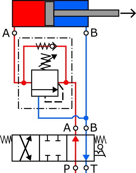
For the sake of simplicity, the hydraulic pump, pressure relief valve and filter have been omitted from this drawing. The directional control valve is in the correct position to extend the cylinder. The fluid flows via the check valve (in the counterbalance valve) to the cylinder.
After switching the directional valve (far-right position), the cylinder is retracted again. The oil is now supplied to the rod side (via port B). The pressure that has built up pushes the counterbalance valve open. The oil flows via the counterbalance valve back to the reservoir.
At the moment the cylinder moves downward faster than oil is being supplied to the rod side (this is called overrunning), the pressure on the rod side, and therefore also the pilot pressure on the counterbalance valve, drops. As a result, the valve is pushed towards the “closed” position by the spring. The volume flow therefore decreases and comes into balance with the volume flow supplied to the rod side.
The counterbalance valve can also act as pressure protection in case of overloading of the actuator due to external forces or by suddenly operating the directional valve: at the moment the directional valve is suddenly set to the middle position while the cylinder is lowering, the counterbalance valve closes immediately. Due to the pressure that then builds up in the cylinder, the counterbalance valve is forced open again from the cylinder side. In this way the counterbalance valve also limits the pressure in the cylinder.
Related page: