EnglishEN
  • NederlandsNL
MVWautotechniek.nl
  • Internal Combustion Engines
  • Electric drive
  • Body
  • Comfort, safety & HVAC
  • Electronics
  • Chassis
  • Transmission
  • Diagnostic Techniques
  • Other
  • Search
  • Internal Combustion Engines
  • Electric drive
  • Body
  • Comfort, safety & HVAC
  • Electronics
  • Chassis
  • Transmission
  • Diagnostic Techniques
  • Other
  • Search

Spool valve

Topic:

  • Hydraulic directional control valve

Hydraulic directional control valve:
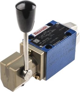
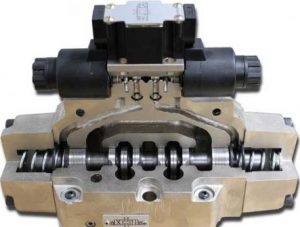
The hydraulic directional control valve, also called a control valve, has the task of regulating the flow direction of hydraulic oil. The directional valve can be operated manually or electrically.

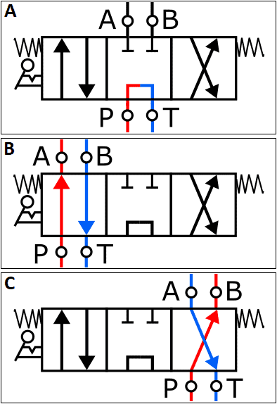
The three images below show the symbol of the directional valve in three different positions:

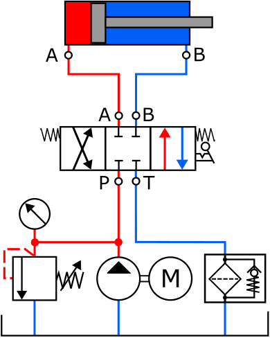
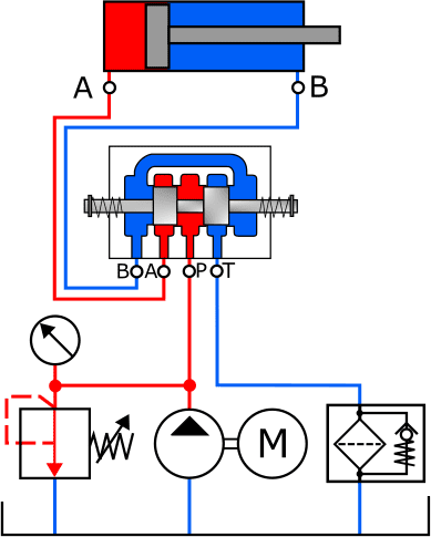
  • A: the directional valve is in the middle position. The hydraulic fluid from the pump is fed directly back to the return line;
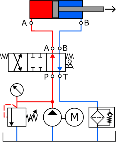
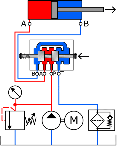
  • B and C: the hydraulic fluid is fed to the cylinder. The difference between B and C is that they are crossed relative to each other. This makes it possible to reverse the direction of movement of the cylinder. More on this later.

The depicted directional valve is a 4/3 valve, which means that it has four ports (A, B, P and T) and three positions (centre, left and right).

The directional valve often has a middle position, which in that case can be seen by the springs on both sides. The springs push the directional valve back into the middle position as soon as it is no longer operated.

The three images below show a manually operated directional valve (left), a cutaway directional valve (centre) and an animation of the operation (right). An explanation of the operation follows in the paragraph below the images.

Manually operated directional valve
Cutaway directional valve
Animation of directional valve operation

As mentioned earlier, the 4/3 directional valve can be set in three positions. In the two images below, the valve is shown in the middle position. The piston is not actuated. On the left you can see the standardised symbol of the valve in the schematic, on the right the actual fluid circuit that is created in this position. The openings between B, A, P and T are closed off by the plungers.

Directional valve in middle position (standardised symbol)
Directional valve in middle position (actual fluid circuit)

When operating the directional valve, the fluid openings change. In this case, the pump pressure is admitted to the left-hand side of the piston (A). The oil on the right-hand side flows via ports B and T, through the filter, back to the reservoir. In the image with the actual fluid circuit, it is clearly visible that the directional valve is pressed to the left, allowing the opening between A and P (red) and B and T (blue) to allow the hydraulic fluid to flow through.

  • The hydraulic fluid enters via port P and leaves the directional valve via port A to make its way to the cylinder;
  • The return channel is also opened: the fluid can flow to the reservoir via ports B and T.
Directional valve pressed to the left (standardised symbol)
Directional valve pressed to the left (actual fluid circuit)

Related page:

  • Hydraulics overview page.
  • Home
  • About
  • Disclaimer
  • Copyright
  • Statistics
  • Projects
  • Workshop
  • Search
  • Home
  • About
  • Disclaimer
  • Copyright
  • Statistics
  • Projects
  • Workshop
  • Search

Copyright 2025 © MVWautotechniek.nl
Designed, written and hosted by Marco van Wijk