Degrees of freedom in wheel guidance:
In a car’s suspension there are several hinges (including on the control arms and shock absorber) that provide the degrees of freedom in the complete suspension. The wheel guidance ensures that the possible degrees of freedom of the potential wheel movements are limited to only one or two. If a wheel is not “held firmly”, it will be able to rotate freely, tilt (in the x and y directions), turn, and move up and down. The wheel is then effectively “loose” from the suspension. It can move in any direction without “guidance”. Each of the movements just mentioned is one degree of freedom.
The suspension, i.e. the wheel guidance, ensures that the freedom of movement is limited to 1 degree of freedom. This means that the wheel can move “freely” in only one direction without influence from the driver. That free movement is the up-and-down motion of jounce and rebound. The wheel can move up and down freely over an uneven road surface.
A car’s suspension is constructed with several line hinges, ball joints, and rotary-sliding hinges. These hinges all influence each other. One hinge too many results in too many degrees of freedom (so the wheel can move in unwanted directions) or in 0 degrees of freedom (the wheel can then no longer move and therefore can no longer jounce and rebound).
Hinges in wheel guidance:
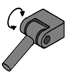
Line hinge:
This line hinge can move in one direction: up and down. This provides 1 degree of freedom.
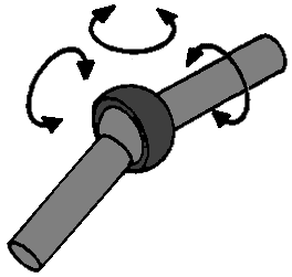
Ball joint:
With this joint the respective parts can make 3 movements relative to each other: a pitch, roll and rotational movement. This joint has 3 degrees of freedom because, when the joint is “loose”, it can make 3 free movements (see arrows).
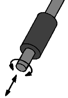
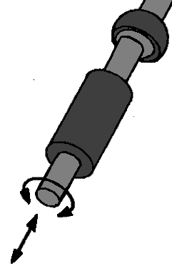
Rotary-sliding hinge:
This hinge can make 2 movements: a rotary movement and an extending and retracting (sliding) movement. In principle this is an example of a shock absorber (of a MacPherson strut). These 2 movements ensure that the rotary-sliding hinge has 2 degrees of freedom.
Guides in wheel guidance:
In order to build a suspension out of various types of hinges, hinges sometimes need to be combined on one object, e.g. a control arm. We then call this control arm a guide. Below are a few examples of these guides:
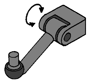
Line hinge with ball joint:
This is a typical example of a control arm, which on the line-hinge side is connected to the body (or subframe) and on the ball-joint side is connected to the steering knuckle. When this entire hinge is loose, it can both move in the direction of movement of the line hinge (1 direction) and in the 3 directions of the ball joint. After all, the line hinge has 1 degree of freedom and the ball joint has 3. Because this section is seen as 1 guide, the degrees of freedom can be added together. The 1 and the 3 then make 4 degrees of freedom.
Double ball joint:
An example of a guide with a double ball joint is the track rod with the inner and outer track-rod ball joints. Each ball joint has 3 degrees of freedom, so because it is 1 guide, these should be added together. However, they have the same self-rotation, because when 1 ball joint makes a rotational movement, the other does as well. So 1 degree of freedom of the self-rotation does not count (see the red arrows). The degrees of freedom for this guide are 6 in total, but in the calculation that follows, you fill in the number 1 at “self-rotations r”. This 1 is then subtracted again in the calculation.
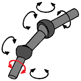
Rotary-sliding hinge with ball joint:
As mentioned earlier, a shock absorber is a rotary-sliding hinge. However, on every MacPherson strut there is also a ball joint on top of that, even though you might not think so at first. At the top of the shock absorber there is also a rubber mount. This rubber provides some freedom of movement of the shock absorber and therefore also has the characteristics of a ball joint. A shock absorber therefore has both the 2 degrees of freedom of the rotary-sliding hinge and the 3 degrees of freedom of the ball joint, which together make 5. Again there is a self-rotation, because the rotary movement of the rotary-sliding hinge is the same movement as the rotary movement of the ball joint. So for the “r” of self-rotation, 1 must be added.
Calculating degrees of freedom:
Based on the data of the suspension, the number of degrees of freedom can be calculated. To correctly fill in this formula, the hinges and guides must be divided into categories:
- L for the number of guides
- g for the number of joints and hinges
- r for the number of self-rotations (as with the double ball joint in 1 guide)
In addition there are the letters:
- k for the number of wheel carriers (in most cases 1, because this is then the steering knuckle)
- εfi for the number of degrees of freedom for the total number of joints and hinges added together.
F = 6 (k + L – g) -r + εfi
Example:
In a suspension there are: k 1 wheel carrier (steering knuckle), L 2 guides, g 5 joints, r 2 self-rotations, εfi 15 total degrees of freedom
In formula form this is:
F = 6 (1 + 2 – 5) – 2 + 15
F = 6 x (-2) – 2 + 15
F = 1
There is therefore now 1 degree of freedom, so this is correct. The wheel can make a pure up-and-down movement.
To clarify this, here is an example with an image of a suspension:
The image below shows a MacPherson strut with the corresponding legend. The letters A, B and C stand for the guides and the numbers 1 to 6 stand for the hinges / joints.
εfi are the degrees of freedom of the joints added together; so 3 degrees of freedom per ball joint (so 4 x 3), 1 degree of freedom of the line hinge and 2 degrees of freedom of the rotary-sliding hinge.
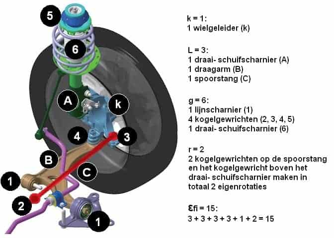
The formula can be filled in as follows:
F = 6 (k + L – g) -r + εfi
F = 6 (1 + 3 – 6) – 2 + 15
F = 6 x (-2) – 2 + 15
F = -12 – 2 + 15
F = -14 + 15
F = 1 degree of freedom