Introduction:
The differential, also called the final drive, makes a speed difference in the drivetrain possible. On this page only the term differential is used.
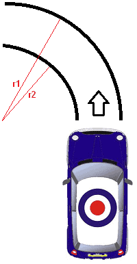
When cornering, one wheel makes more revolutions than the other wheel. When a car turns left (as in the image below), the right wheels will make more revolutions than the left wheels (r1 > r2). A speed difference therefore arises. A differential ensures that this is possible.
In front-wheel drive cars, the differential is located in the gearbox. In rear-wheel drive cars it is located at the rear axle, between the rear wheels. A driveshaft then runs from the gearbox to the rear, to the differential.
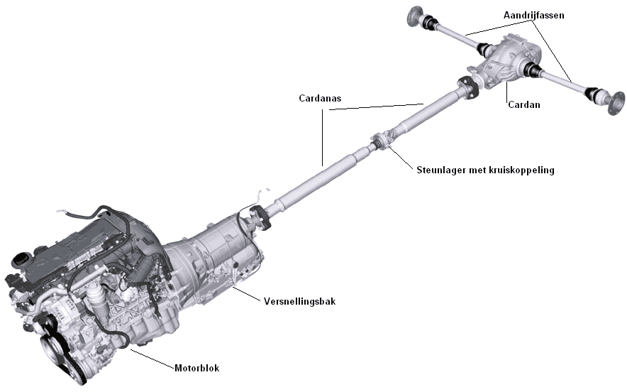
The image below is of a rear-wheel drive car. The shaft between the gearbox and the differential (final drive) is called the propeller shaft or intermediate shaft. This is described separately on the propeller shaft page. Two drive shafts are mounted to the differential which drive the rear wheels.
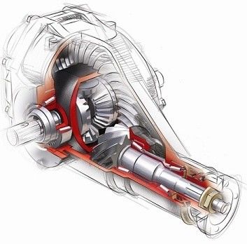
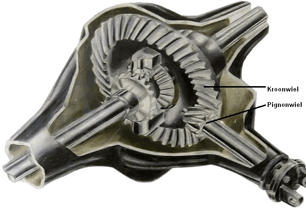
Ring and pinion gear:
The ring and pinion gear in the differential are mentioned separately because these parts must be adjusted very precisely after any work. The pinion gear is attached to the driveshaft. The engine and the gearbox provide the drive for the driveshaft and the pinion gear drives the ring gear. Adjusting the ring and pinion gear is highly specialized work. Using factory specifications and measuring / adjustment equipment, the gears must be set to each other. Good adjustment results in the least noise and the longest service life.
Operation of the differential:
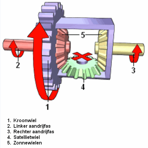
Ring gear 1 is driven by the pinion gear from the engine/gearbox. When driving straight ahead, drive shafts 2 and 3 will rotate at the same speed and planet gear 4 will not rotate around its own axis.
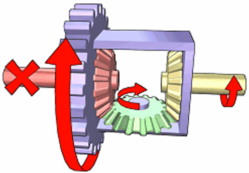
In the situation in this image, the left drive shaft is stationary. This may be because the left wheel is on asphalt and the right wheel is on an unpaved road. The wheel on the unpaved road will in this case be spinning.
The planet gear now rotates around its own axis and the full drive force is transferred to the right drive shaft. The left one is now stationary. A similar situation also occurs when driving through a bend, when the tire pressure on one side is lower, the tire tread pattern differs greatly and when the road surface is not completely flat.
Disadvantages of a differential:
The fact that the differential makes differences in rotational speeds between the wheels possible is, under certain circumstances, also a major disadvantage. When one of the driven wheels loses grip, the total drive is lost. When a car has one wheel on asphalt and one wheel in mud, the wheel in the mud will be driven 100% and the wheel on the asphalt (with the most grip) will remain stationary. That is because the planet gear starts to rotate quickly and the wheel with the least resistance will be driven the most.
Adjusting the ring and pinion gear:
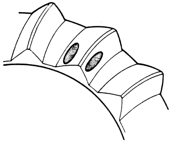
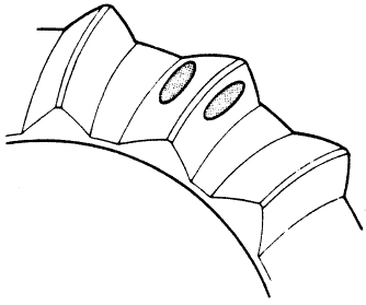
The height and distance of the contact surfaces of the ring and pinion gear can be adjusted. The images show the consequences of incorrect adjustment.
By coating a quarter of a revolution of the ring gear with special grease (which dissolves in oil), the contact pattern between ring and pinion gear can be determined. By rotating the pinion gear a number of turns back and forth, the contact pattern becomes clear (see images). By adjusting and rotating several times, the whole can be set to the ideal contact pattern.
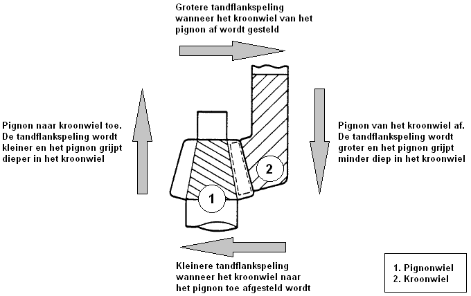
The fact must be taken into account that the load on the drivetrain also causes the contact pattern to shift. As the load increases, the contact pattern moves more towards the outside of the ring gear (right-hand image above). With light load the contact pattern moves more inwards. When adjusting, the contact pattern must end up in the middle. Always consult the factory data for the dimensions.
Incorrect adjustment causes (sometimes extremely) a lot of noise in the drivetrain, such as a whistling, howling sound. Wear will also increase. The differential can fail after just a few thousand kilometres if it has been adjusted carelessly (or not adjusted at all). Of course, a loud noise has preceded that.
LSD (Limited Slip Differential)
To prevent the situation described above, it is useful in some cases to (partially) disable the operation of the differential. This is called locking. When a differential is locked, the drive to both shafts is equal. The planet gear is immobilized, or both sun gears are coupled together. There are various developments with multi-plate clutches, viscous couplings and dog clutches.
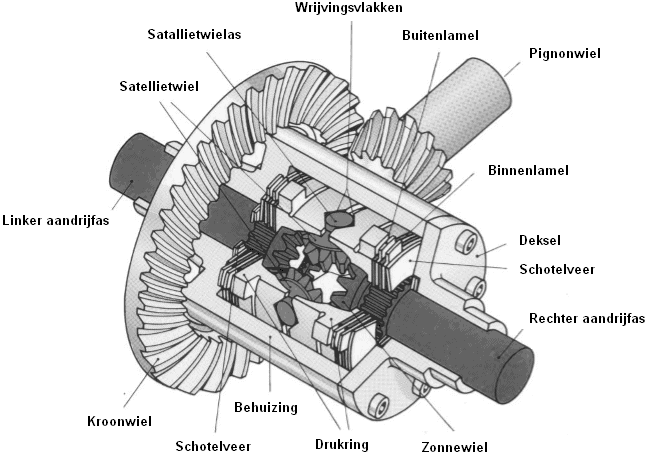
In the image below an LSD (Limited Slip Differential) can be seen. This is a differential with increased internal friction. Between the outer flat surfaces of the cone-shaped sun gears of the axle shafts and the differential housing, multi-plate clutches are fitted.
The pressure rings in the LSD are on one side connected to the differential housing and on the other side axially movable. The pressure rings are wedge-shaped on the inside due to the crowned shape of the planet gears. The inner plates (dark-coloured in the image above) engage with their internal teeth in the splines of the axle shafts. The external teeth of the outer plates engage in the longitudinal grooves of the differential housing. The outer plates therefore cannot rotate.
When driving straight ahead, the ring gear and the drive shaft rotate at the same speed and there is therefore no friction. When one of the wheels has too little grip and therefore rotates faster than the other wheel, a speed difference arises between the conical surfaces of the pressure ring. The pressure ring is pressed against the plates and a load-dependent friction torque is created between the outer plates (which are locked by the differential housing) and the fast-rotating inner plates that are connected to the drive shaft.
The more modern electronically controlled systems are developments based on the self-locking systems. The previously described pressure rings present in the self-locking systems are then replaced by hydraulically operated annular cylinders. With the aid of electronics, the multi-plate clutches are operated.
Torsen differential
The Torsen differential (‘torsen’ is an abbreviation of ‘torque sensing’) is in principle a symmetrical differential. When both output shafts rotate at the same rotational frequency, the drive torques in these shafts are equal. If differential action occurs for any reason, the drive torque to the faster rotating output shaft decreases and to the slower rotating shaft increases. Here too, an internal friction torque basically arises that on the one hand reduces the output torque and on the other hand increases the output torque. The operation is based on the self-braking behaviour of the worm and worm wheel gear that arises from choosing the correct lead angle of these gears.
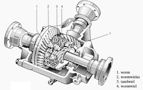
The axle differential in the image below is bolted to the ring gear. The worm wheel shafts are mounted in the differential housing. The worm wheels, which are connected in pairs by cylindrical gears, can rotate freely around their shafts.
Three sets of two worm wheels each are built in. One worm wheel of each set meshes with the worm that is mounted with splines on the wheel drive shaft to the right wheel; the other worm wheel meshes with the worm on the wheel drive shaft to the left wheel.
When driving straight ahead (forwards or backwards), when there is no differential action, both shafts rotate at the same speed. The differential housing carries the worm wheels, which in turn drive the worms with the wheel drive shafts. The two worm wheels want to rotate in the same direction due to their lead direction, which is not possible because of the connection with cylindrical pinions. The differential therefore now rotates as one block and ensures a symmetrical torque distribution (50% – 50%).
When differential action occurs, for example when driving through a bend, or when one wheel spins, one worm will rotate faster and the other worm slower than the differential housing. A greater torque is now supplied to the slower rotating wheel than to the faster rotating wheel. The faster rotating worm drives the corresponding worm wheel and with it the worm wheel that drives the worm to the slower rotating wheel. To the slower rotating wheel the torque is further increased by the partially self-braking effect during drive by the worm wheel in the direction of the worm. By choosing the correct lead angle on the worm, the desired torque distribution, i.e. the locking factor, can be obtained.
The Torsen differential has no influence on any ABS function, because the locking effect only occurs under load, i.e. when the accelerator is pressed.
Especially in racing, with drifting, the differential is locked. When this is technically not possible with certain cars, the planet gear is welded to the sun gears. In this inexpensive way, the differential is always locked. The disadvantage is that it is hardly possible to drive on public roads, because the wheel that makes the fewest revolutions in corners will start to slip. The risk of damage to the drive shafts and CV joints is also greater.
Another way is to have the ESP (Electronic Stability Program) intervene. This system brakes the spinning wheel by briefly applying the brake caliper. By braking the spinning wheel, more power will automatically be transferred to the other wheel due to the operation of the differential. In this way that disadvantage is also eliminated. This is sometimes also called an electronic differential lock function.
Maintenance and faults of a differential:
Nowadays, a differential often contains “lifetime oil”. The manufacturer indicates with this that the oil does not need to be changed periodically. Some manufacturers do specify a change interval in a certain number of kilometres. This interval must not be exceeded. Even with differentials with lifetime oil it is a good idea to change the oil from time to time. All oil comes into contact with oxygen and undergoes an oxidation process. The lubricating effect decreases. Therefore it is good to change this oil at a certain mileage (e.g. at 150,000 km).
Faulty differentials, where the bearings are defective or the clearance on the ring and pinion gear is not correct, cause a lot of noise in the drivetrain. In most cases the differentials can be overhauled. During overhaul, among other things, the tooth surfaces of the ring and pinion gear are measured and the bearings replaced. If the tooth surfaces are too badly worn, the parts will have to be replaced. Replacing the ring gear is often very expensive.
Adjusting differential bearing preload:
The bearings in the differential must be installed with a specified preload. This value is determined by the manufacturer of the differential. With both too little and too much preload, the bearing may fail over time. Think for example of excessive axial load, which can cause the bearing to become too hot. When overhauling the differential or replacing the bearings, the preload must therefore always be checked and, if necessary, adjusted. By performing measurements it can be determined what thickness the shim (between the bearing and the seal carrier) must have.
Below are examples of the measurements that need to be taken.
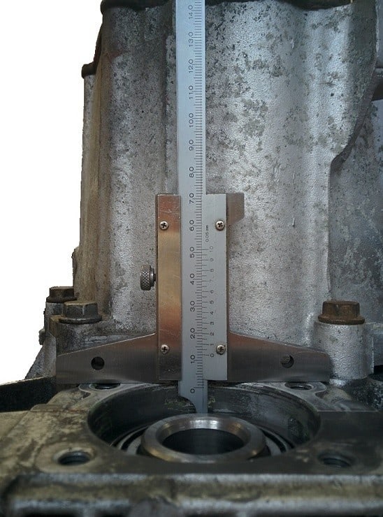
Using a depth gauge, the distance between the outer side of the gearbox housing and the bearing must be measured. The value measured in the photo is 12 mm.
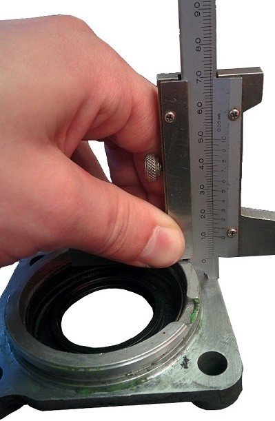
This depth gauge can also be used to measure the height of the shoulder of the seal carrier. The value measured in the photo is 10.0 mm.
During assembly, the shoulder of the seal carrier is mounted into the differential housing. By subtracting the two values just measured from each other, the distance between the differential bearing and the shoulder of the seal carrier is determined: depth – height = 12.00 mm – 10.00 mm = 2 mm.
If a 2 mm shim is placed between the differential bearing and the seal carrier, the bearing would be installed without preload.
That is of course not the intention; a thicker shim must be installed in order to mount the bearing under preload. The preload is specified by the manufacturer. This can, for example, be 0.25 mm.
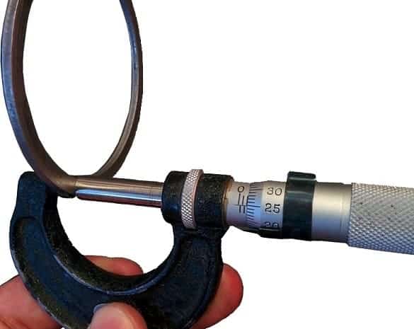
The shim that must be installed in this case is the measured distance + the preload, so: 2 mm + 0.25 mm = 2.25 mm. When the shim with a thickness of 2.25 mm is installed, the preload is set correctly. The suitable shim must be found in a box containing various shim sizes. A vernier caliper can be used to find the correct shim.
In the image below you can see that the shim has a thickness of 2.25 mm. This is therefore the correct shim. More information about measuring with the vernier caliper can be found on the page “Mechanisch meetgereedschap“.
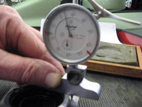
The measurements of the depth of the bearing and the height of the shoulder of the seal carrier in the images above were taken with a depth gauge. However, these measurements can also be taken with a dial gauge. An explanation of measuring with the dial gauge is also given on the page “Mechanisch meetgereedschap“.
The measured values in the images below do not correspond to the measurements above. The photos are also very blurry. These will soon be replaced with new images in which the measurements are shown correctly.
The values from the dial gauge and from the depth gauge must match. So in principle it does not matter which tool is used to carry out the measurement, provided both measuring tools are available. For example, in a practical exam it may well be that only one type of measuring tool is provided. It is therefore important to be able to work with all measuring tools: the vernier caliper, the micrometer and the dial gauge.