Introduction:
A diode is added to many electronic circuits, for example as a rectifier in an alternator or radio, or as a freewheel diode with a coil. This page explains the operation and the different functions.
Diode as polarity protector and rectifier:
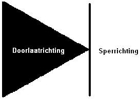
The diode in a system provides rectification. The current can only flow in one direction and is blocked in the reverse direction. This is clearly illustrated in the image below. This is often done to protect components against incorrect connections (as a so‑called polarity protector, when + and – are swapped). If the power supply and ground of a component are reversed, the diodes inside ensure that the voltage is blocked to prevent, for example, the circuit board from being damaged.
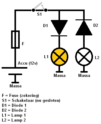
In the illustration below, the basic function is shown. Diode D1 is conducting, D2 is reverse‑biased. It is easy to remember that current flows in the direction in which the arrow points. With D1, the current is allowed through and reaches lamp L1. The lamp will now light up. Lamp L2 will not, because this diode is reverse‑biased. Instead of a lamp as in this example, there can be all kinds of components that can be irreparably damaged when connected.
Diodes are also used in alternators for rectification. In an alternator, AC voltage is generated, which must be converted to DC voltage. By using multiple diodes (in the diode bridge), this is made possible. For more information about diodes as rectifiers in an alternator, see the chapter on rectifier diodes on the alternator page.
Freewheel diode:
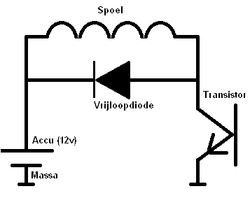
A high voltage is induced in a coil, for example in an ignition coil. The voltage running through the coil is switched on and off by the transistor. However, when the transistor no longer conducts (the drive current to the base is switched off), the coil is still full of residual energy. The coil is not able to be instantly “empty” after the transistor is switched off. After switching off, an induction voltage is always released, which can be many times higher than the on‑board voltage of 14 volts.
The result is that due to this induction voltage, the transistor remains switched on. Because of this induction, the coil keeps the transistor conducting, even though it is switched off (at the base of the transistor).
To prevent this, a freewheel diode is added to the system. When the transistor now switches off, the induction voltage flows via the freewheel diode to the positive terminal of the coil. Because the induction voltage no longer reaches the transistor, it remains switched off.
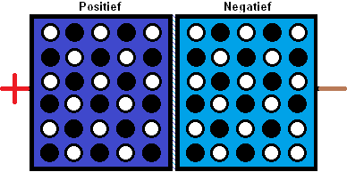
Technical operation of a diode:
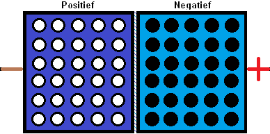
A diode consists of a plate of Positive silicon and a plate of Negative silicon. In the plates there are holes, with positive ions and negative electrons. These move as the direction of current changes.
These P and N silicon plates are placed against each other. The current flows from positive to negative (forward direction). If the current wants to flow from negative to positive (reverse direction), it is blocked. In the images below you can see how this happens:
Reverse direction:
In the image below, the diode is reverse‑biased. The – is now, for example, connected to a voltage source and the + to ground. The diode now ensures that no current flows from – to +.
The negative electrons have now all moved to the plate with the Negative silicon. The plate with Positive silicon, thus with the positive ions, does not conduct. The “holes” are empty, so no conduction and therefore no current transfer can take place.
Forward direction:
The current flows from + to -, so in the image from left to right. The positive electrons and the negative electrons are mixed. The holes in P are now filled by the negative electrons, so a conductive action (the forward direction) is created. However, there is a voltage drop, because there is still some resistance (the conduction is not completely ideal). This voltage is called the diffusion voltage, and is always about 0.7 volts.
Related pages: