Drive shaft:
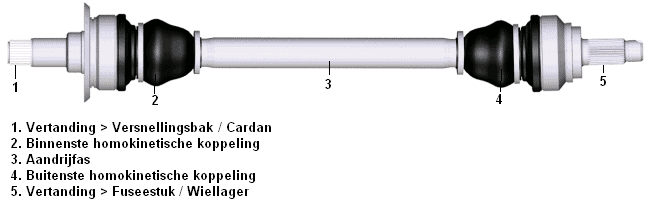
A drive shaft transmits the driving forces to the wheels. In front‑wheel‑drive cars, the inner side of the drive shaft is connected to the gearbox and the outer side to the steering knuckle. In the image below, the shaft at number 5 passes through the wheel bearing, which is also splined. The splines interlock, causing the wheel bearing to rotate together with the flange when the drive shaft is driven.
In rear‑wheel‑drive cars, the gearbox is usually mounted longitudinally to the engine and, via the propeller shaft, drives the differential, which distributes the power to both drive shafts so that the rear wheels are driven. Here too, the splines (fig. number 5) are mounted in the wheel bearing.
Sections 1 and 5 in the image remain horizontal. Because the wheel must be able to move up and down with the suspension and perform steering movements, moving parts are required in the drive shaft. These movements are made possible by using constant velocity joints. One end of the drive shaft is attached to the gearbox or differential with a constant velocity joint, and the other end with a constant velocity joint in the unsprung part of the strut.
Unsprung means that the part is located below the spring and therefore follows the road surface (potholes / bumps). The sprung part of the car is everything that rests on the springs (and thus moves with the compression and rebound of the car). There is therefore movement during compression and rebound and a height difference relative to the engine/gearbox and the steering knuckle in which the shaft is mounted. So a completely straight shaft cannot be installed. The shaft will always have to form a certain angle on both sides. When the car is heavily compressed, the drive shaft (section 3) will be at a steeper angle than when the car is at full rebound.
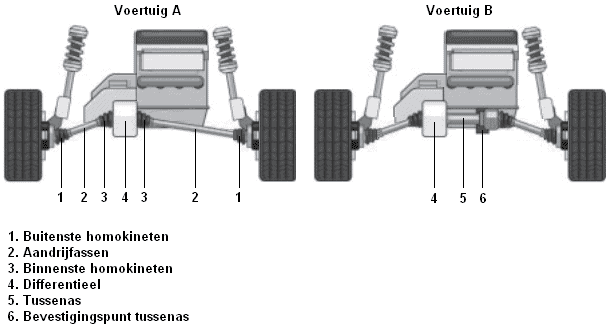
Because a long drive shaft can be disadvantageous for the design of the car, an intermediate shaft can also be fitted. This is clarified in the image.
With a chassis where a drive shaft from vehicle A does not fit – the subframe or the control arm is in the way – an intermediate shaft can be used. The intermediate shaft, as shown in vehicle B, is mounted horizontally in the differential. On the right‑hand side of the intermediate shaft, the inner CV joint of the drive shaft is mounted. At this point the drive shaft is attached to a fixed point on the body or the subframe.
As a result, the right‑hand drive shaft is positioned at a greater angle than in vehicle A.
Constant velocity joint:
A CV joint is also called a Rzeppa joint (named after the inventor Alfred Hans Rzeppa). A CV joint makes it possible to drive the wheels while the vehicle can move up and down with the suspension and steer. The joint is designed so that the angle at which the drive shaft is positioned has no effect on the angular velocity at which the shaft rotates. The speed of the inner CV joint is exactly the same as that of the outer one. With a universal joint this is different; it produces a non‑uniform motion.
In the image below you can see a CV joint that is used on the wheel side. The drive shaft is visible at the bottom left. Also visible are the ball bearings and the splines, because the CV joint is positioned here at an angle.

A protective boot is fitted around the constant velocity joint, as can be seen in the upper image. This boot contains special molykote grease. The boot is very flexible, but it can sometimes tear, causing the grease to leak out. It is important to replace a torn CV boot / drive shaft boot as soon as possible, because the grease will disappear and sand etc. can get in. Sand and dirt will stick to the grease. As a result, the constant velocity joint will fail quickly. When a constant velocity joint is defective, a ticking noise can be heard on the wheel side when driving through a corner, and a vibration will be felt on the gearbox side during acceleration.
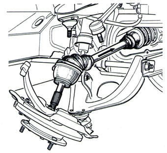
When replacing the dust boot, the drive shaft must be removed. Sometimes it is possible to replace the boot while the drive shaft is still mounted to the final drive (the gearbox or the differential). The steering knuckle must be disconnected at the top or bottom. Often the outer track rod end also has to be removed from the steering knuckle. This is shown in the image.
When the drive shaft has been removed from the steering knuckle, first the hose clamp of the boot must be loosened. The boot can then be slid off the CV joint, after which the CV joint can be removed from the drive shaft. Often the CV joint can be knocked off with a hammer; the circlip is on the drive shaft, inside the CV joint. Sometimes there is also a circlip on the drive shaft that must first be removed before the CV joint can be slid off. Consult the manufacturer’s repair manuals for this.
When installing the CV joint, it must be ensured that the circlip is in place; when the circlip is on the drive shaft and the CV joint has to be slid over it, the CV joint must be pushed far enough onto the shaft. If this is not the case, the CV joint will slip off the shaft during steering movements. To check whether the CV joint and the circlip are properly seated, you can feel for play in both parts; there should be a very small amount of play. If the CV joint is completely tight on the shaft, it is possible that it is not yet fully seated.
Tripod joint:
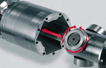
On the inner side (the gearbox or differential side) a tripod joint is often used. This is not always the case; the CV joint described above is also frequently used. A tripod joint works differently and can be recognized by its larger housing. The image below shows the tripod joint.
The tripod joint often has three rotating rollers that slide into a groove in the housing. The rollers make it possible for the drive shaft, just like with the Rzeppa joint, to make a perfectly rotating movement. The advantage of this joint is that the drive shaft can move back and forth over a large distance within the housing. When worn, this joint is prone to causing vibrations. The splines in the housing will deform, forcing the rollers to make a different movement than intended, resulting in vibration. This vibration can be felt in the steering wheel during acceleration and sometimes throughout the entire car. By removing the drive shaft, it is very easy to determine whether the tripod joint is worn or whether the cause must be sought elsewhere. After removing the grease, you can feel any irregularities in the housing by hand; if a small pit or a burr can be felt, it is advisable to install a new joint.
Sometimes only one of the two tripod joints is defective. Because these joints are very expensive, it is worthwhile to first check which joint is actually worn before replacing both sides as a precaution.
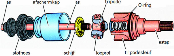
The image below shows an exploded view of a tripod joint.
Related page: