EBS powered vehicle:
EBS is an abbreviation for “Electronically Controlled Brake System” and is found in truck combinations of powered vehicle and trailer with a pneumatic brake system. With the conventional pneumatic brake system the driver operates the pneumatic service brake directly with the foot brake valve. With EBS there is – in a fault-free situation – no direct pneumatic actuation.
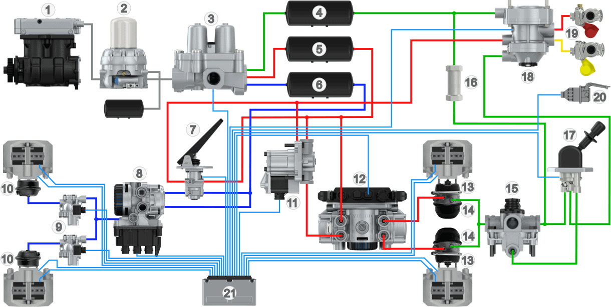
The image below shows an overview of the pneumatic brake system with EBS. We recognize most components from the pneumatic brake system which is discussed in detail on other pages on this website. In the unit beneath the brake pedal there is a so‑called brake value sensor (7), which uses sensors to register the pedal travel. This can be done by measuring the distance the brake pedal travels using distance sensors (Knorr) or by means of potentiometers (Wabco). The pedal travel is sent by sensors to the EBS computer (20). Via CAN bus the EBS computer controls the front axle modulator (8) and rear axle modulator (12) to pass the desired brake pressure to the brake boosters. On the front axle we find separate ABS solenoid valves (9), which are integrated in the rear axle modulator. The EBS computer sends the brake signal via the connector (20) to the trailer or semitrailer.
Legend:
- Compressor
- Dryer
- Four-circuit protection valve
- Air reservoir circuit 3
- Air reservoir circuit 1
- Air reservoir circuit 2
- Foot brake valve / brake value sensor
- Front axle modulator
- ABS valves
- Diaphragm cylinders (front)
- Redundancy valve
- Rear axle modulator
- Diaphragm cylinders (rear)
- Spring brake cylinders
- Relay valve
- Check valve
- Parking brake valve
- Trailer control valve (ECE valve)
- Duomatic couplings (red = supply, yellow = control)
- Trailer / semitrailer plug
- EBS computer
The brake pressure to the diaphragm cylinders depends on:
- The pedal travel and thus the desired deceleration: The EBS computer calculates the desired deceleration based on the pedal travel and, with the calculated brake pressure, controls the modulators of the front axle, rear axle and the trailer. This ensures that, with a very fast response time, the correct air pressure is sent to the brake boosters. In the modulators the pneumatic brake pressure can be held, increased and decreased. Trucks with an EBS system can brake hard with little pedal force;
- The harmonization a.k.a. brake balance: The electronic control of the EBS ECU and the front and rear axle modulators ensures good harmonization between powered vehicle and trailer. The output brake pressure can be controlled separately for each line;
- The load: Because the modulators regulate the pneumatic brake pressure, an ALR on the powered vehicle is unnecessary. The bellows pressure is measured by pressure sensors in the modulator.
- The brake lining wear: When brake pads hardly wear, glazing can occur due to age. To ensure gradual brake wear, the brakes can be actuated more or less per axle.
Modern vehicles can be equipped with an automatic braking system, for example in active cruise control, or collision detection to prevent a crash. Because the modulators control the pneumatic brakes electrically, braking interventions can take place independently of the driver.
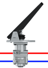
Foot brake valve with brake value sensor:
The foot brake valve consists of an electrical and a pneumatic section.
- Electrical: sensors measure the pedal travel and thus the driver’s desired brake deceleration. Wabco uses switches and distance sensors, where the switches register the pressing of the pedal, and the distance sensors measure the piston stroke that occurs when the brake pedal is pressed. Knorr uses potentiometers to determine the position. As with the accelerator pedal, the signals from two potentiometers are compared to measure the exact position;
- Pneumatic: when a fault is detected and the electric brake system fails, or is marked as unreliable by the EBS ECU, the pneumatic system is used as a backup. In this case the driver must operate the brake pedal with more force. The operation of the pneumatic section is described on the page: service brake.
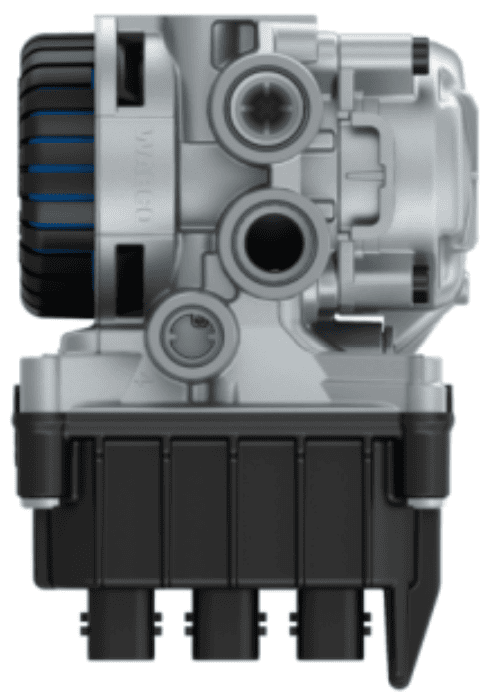
Front axle modulator:
The front axle modulator receives the electrical brake signal from the EBS computer and converts this signal into the desired brake pressure. The opening between the air pressure in the reservoir is passed on to the ABS valve, and thus to the diaphragm cylinder. The electrical signal from the ECU determines to what extent the modulator passes on the brake pressure. This makes the front axle modulator an electrically controlled relay valve.
In the image, the ABS valve is shown as a separate component. This is used, among others, by Wabco. With Knorr, we see two front axle modulators with integrated ABS valves.
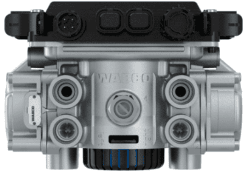
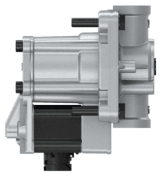
Rear axle modulator:
Just as with the front axle modulator, the desired brake deceleration is sent by the EBS computer to the rear axle modulator to send the desired brake pressure to the diaphragm cylinders. The ABS valves are integrated in the rear axle modulator.
The ALR (load‑sensing valve) that we encounter in conventional pneumatic brake systems is no longer present in the EBS system. Instead of the ALR, the bellows pressure is measured by pressure sensors in the rear axle modulator. To make this possible, there are air lines between the air bellows and the rear axle modulator.
Redundancy valve:
The redundancy valve acts as a relay valve and is used by Wabco as a backup to ensure that the vehicle can always brake safely under all circumstances. Under normal conditions, the EBS computer controls the redundancy valve, which interrupts the connection between the foot brake valve and the rear axle modulator.
In the event of an electrical fault, the redundancy valve ensures that the brake pressure to the brake cylinders is limited so that the vehicle can continue to brake safely. It does this by automatically switching the valve to an emergency mode in which it directs the air pressure directly from the foot brake valve to the brake cylinders of the rear axle.
ABS/EBS ECU:
The ABS/EBS ECU processes the sensor signals from, among others, the brake value sensor, wheel speed sensors and the status of all connected actuators. With this information, the desired brake pressure is calculated and sent to the modulators of the front axle, rear axle and trailer to direct the brake pressure to the brake cylinders. In the case of spinning or locking wheels, the ABS valves are actuated to reduce, hold or increase the brake pressure.
ABS/EBS connector:
On the powered vehicle there is an ABS/EBS connector, to which the cable of the trailer can be connected. Once connected, the EBS computer in the powered vehicle can control the trailer modulator to brake electrically. When a fault is present, the trailer receives brake pressure via the control line (yellow duomatic coupling) to brake it in the conventional way.
EBS trailer:
The trailer modulator (8) has an integrated ECU and receives data from the powered vehicle via CAN bus communication through connector (1). The supply (2) and control couplings (3) are identical to the conventional pneumatic brake system. When the plug is not connected or when a fault occurs, the brake system will operate according to the conventional control method, which is described on the page: trailer brake system. In that case the ABS system will still operate.
Just like the rear axle modulator of the powered vehicle, the trailer modulator measures the bellows pressure to determine the load. This allows the brake pressure to the diaphragm cylinders to be adjusted to the load.
The image below shows an overview of the components of the trailer’s EBS system.
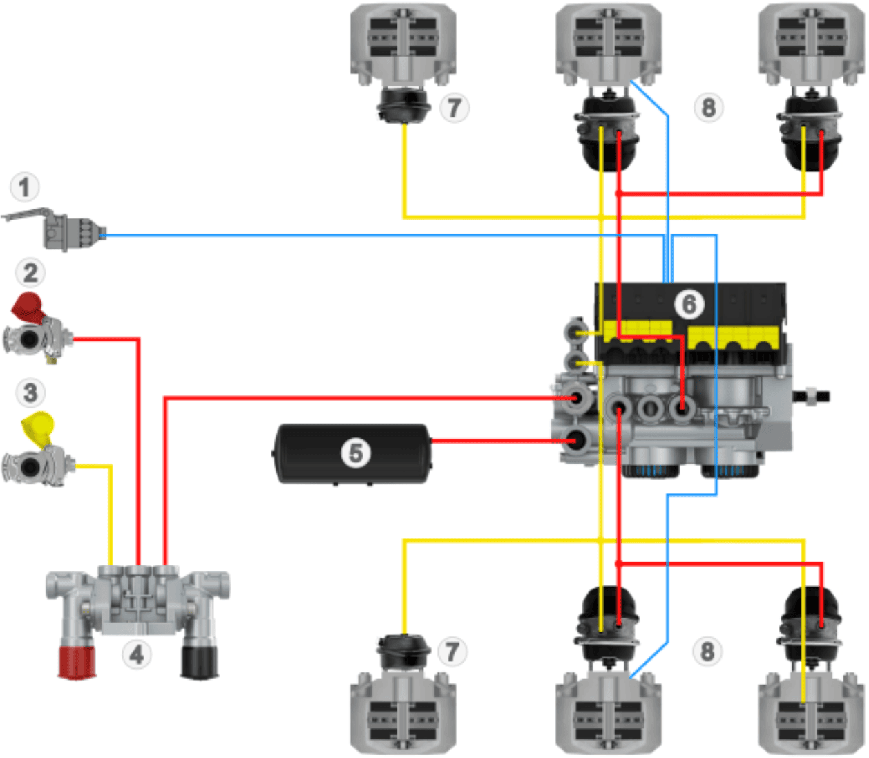
Legend:
- ABS/EBS connector
- Supply duomatic coupling
- Control duomatic coupling
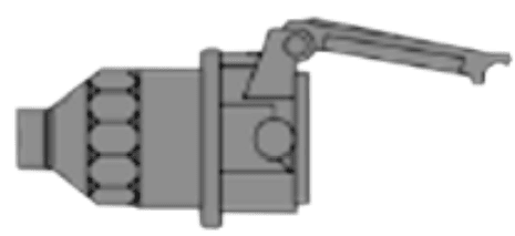
- PREV (Park Release Emergency Valve)
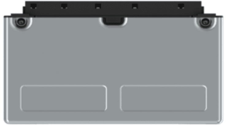
- Air reservoir
- Trailer modulator
- Diaphragm cylinders
- Combined diaphragm and spring brake cylinders
Related page: