Interior fan:
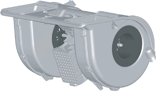
The image below shows an interior fan. This component is also called a heater motor or blower motor.
In the middle of the blower are the impeller blades that blow the ventilation air into the interior. The ventilation air is drawn in at the side of the motor and is blown through the heater radiator or the air conditioning evaporator via the oval ducts above (which are mounted directly after the interior fan in the heater housing).
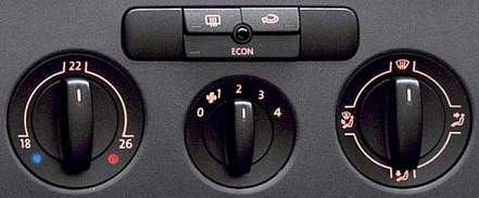
The images below show the manual control panel (left) and the automatic one (right). The automatic control has the advantage that fan speed, outlet temperature, demisting and recirculation are automatically adjusted to the current conditions.

Duty-cycle controlled interior fan:
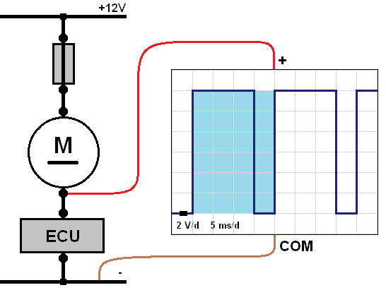
Modern ventilation systems are increasingly equipped with a duty-cycle controlled interior fan. The advantage of this type of control is that there is no loss, as is the case with a heater resistor. With a duty-cycle controlled interior fan, the ECU (the control unit) continuously switches the electric motor on and off. We can measure this with an oscilloscope.
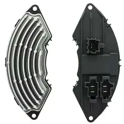
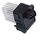
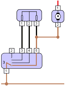
The bottom-left image shows both sides of the switching section of the heater motor. This component is mounted on the heater motor. The housing contains a switching transistor that is controlled by the ECU. The switching transistor supplies the electric motor with either power or ground. The transistor becomes very hot in use. The cooling fins dissipate the heat to the airflow moved by the fan.
The image on the right shows the scope pattern in which the period time (blue) is displayed.
- Switched off when the voltage on the ground side is 12 volts during this period. The electric motor has not used the voltage.
- Switched on when the voltage on the ground side is 0 volts during this period. At that moment, the electric motor has used the 12 volts to run.
The on-time is 25% of the total time, so the interior fan runs at a low speed. The longer the electric motor is connected to ground, the faster the fan will run. If the ECU connects it fully to ground, it will run at maximum speed. On the page duty cycle and PWM control you will find more explanation about different control methods and signal processing.
Possible faults in the duty-cycle controlled system:
- Input to the ECU not OK, for example the control unit containing the buttons and switches. This may be equipped with LIN-bus communication. Check whether communication is taking place.
- Power supply (positive or ground) to the ECU not OK. The ECU does not switch on.
- Power supply to the fan not OK. Check whether the fan is switched on the positive side or on the ground side and measure this. In the diagram above, the electric motor is ground-switched, so with the ignition switched on there must always be 12 volts measured at the input of the motor.
- Defective switching section. First check the wiring: are the power supply and ground at the switching section OK? Is there communication with the ECU? The ECU is often located behind the control buttons. If all measurements are OK, but the switching section does not drive the electric motor, there is a good chance that the switching section with transistor needs to be replaced.
Control of the interior fan by means of a series resistor:
The interior fan obviously needs to be supplied with voltage in order to operate. With a voltage of 12 volts, the fan will run at maximum speed. That corresponds to position 4 to which the knob is turned (or the maximum value on the digital display of the automatically controlled ventilation). When positions 1, 2, or 3 on the control switch are selected, the interior fan must run more slowly. The voltage must then be reduced. The series resistor provides this. The three images below show different heater resistors.


The heater resistor becomes very hot; therefore it is located in a duct through which air is blown. It is often near the interior fan, or even in the same housing. The passing air cools the heater resistor.
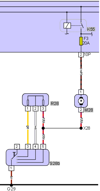
The following components are shown in the interior fan circuit diagram:
- K55: interior fan relay;
- F3: 20 A fuse;
- M28: interior fan;
- R28: series resistor;
- S28b: four-position switch.
The connector codes and designations can also be seen:
- 10P, 2: connector on the electronics box, position 2
- X28: wire connection;
- G29: ground point.
The abbreviations of the wire colours are as follows:
- sw/rt: black/red;
- rt/bl: red/blue;
- ws: white;
- ge: yellow;
- br: brown.
The positive wire of the interior fan is connected to the relay via a fuse. The relay is energised when the ignition is switched on. That means that with the ignition on, the interior fan always receives a positive supply. The current flows via the series resistor and the switch to ground. So the interior fan is ground-switched.
The speed of the interior fan is determined by which and how many resistors the current flows through.
Below, three situations are shown in which the switch connects the interior fan to ground.
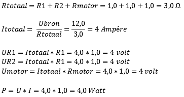
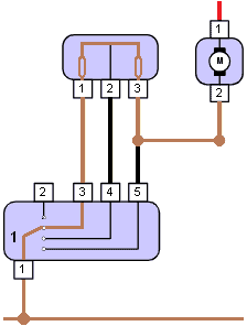
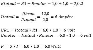
Position 1: The switch is in position 1. The current flows via terminal 3 of the heater resistor through two resistors that are connected in series. The two resistors cause a total voltage drop of 8 volts at a system voltage of 12 volts. The formula below shows that in this position the interior fan operates at a voltage of 4 volts.
Position 2: When the switch is in position 2, the current flows through only one resistor. The formula therefore changes slightly. We omit the value of R2. In this case there is less voltage drop and the interior fan runs at a higher voltage and current. It will run faster.
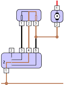
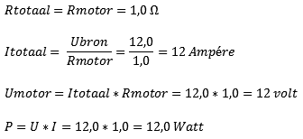
Position 3: In this position the heater resistor is not used. The current leaves the motor and goes directly to the switch. This connects the blower directly to ground. It therefore runs at the highest setting. The formula below takes into account the internal resistance of the electric motor. The voltage across the electric motor is now 12 volts.
Diagnosis of fan motor with series resistor with seven possible faults:
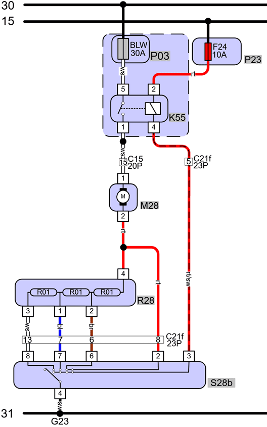
The previous paragraph explained how the heater resistor ensures that the fan speed can be controlled. This paragraph discusses possible faults and explains how a diagnosis can be made using measurements. The diagram shown alongside is used for this.
- at the top of the diagram we see terminal 30 (constant +) and terminal 15 (switched +);
- below that we see P03 and K55 (fuse and relay) with a separate fuse (P23) in the fuse holder next to them;
- pin 1 of the relay (DIN designation 87) supplies voltage to the fan motor M28;
- the fan motor M28 is in series with the series resistor R28;
- the position of switch S28b determines how the ground from the fan runs through one or more resistors, or bypasses them;
- in position 4 the motor is connected directly to ground without any resistor in series, and it runs at maximum power;
- in positions 3 to 1 one more resistor is added in series each time, causing the motor to run more slowly.
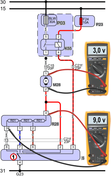
The images below show measurements in the four different switched positions when no fault is present. It can clearly be seen that when the switch is in position 1, a lot of voltage (9 volts) is used in the resistors, so that only 3 volts remain for the motor to run.
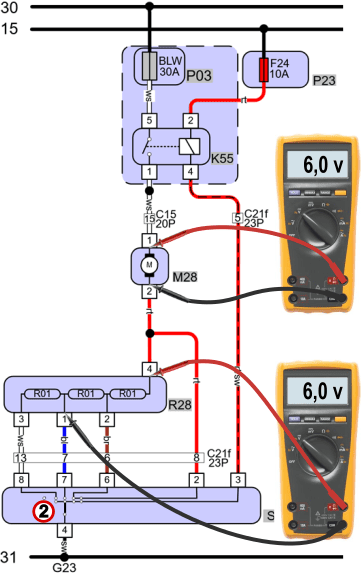
In positions 2 and 3 the voltage used in the resistors is lower because the current has to flow through fewer resistors.
In position 4 the current bypasses the series resistor, and the resistors no longer consume any voltage. The motor now runs on the full 12 volts.
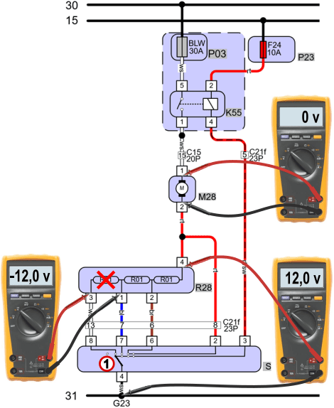
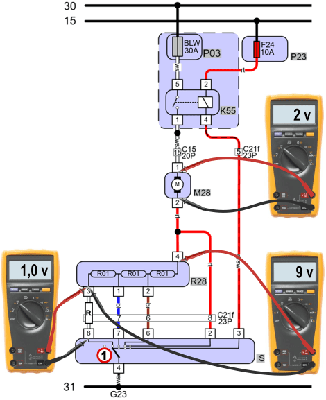
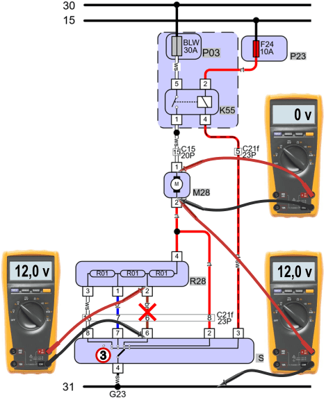
Malfunction 1: fan does not work in position 1, in other positions it works properly.
A heater resistor can fail due to heat. A well-known consequence of a faulty heater resistor is that the fan only works in position 4, and remains off in all other positions. In this case, one resistor is defective. By measuring voltages we can find out which resistor has burned out.
- the voltage across the fan motor is 0 volts. This is the reason why it does not operate at all;
- the voltage difference across the resistor relative to ground is 12 volts, which indicates an interruption somewhere in between;
- the voltage difference across the leftmost resistor is -12 volts. We measure this on pin 3 relative to pin 1. That tells us there is an interruption between those two measuring points;
- the value is negative because the voltage on the black test lead is 12 volts higher than on the red test lead;
- conclusion: the heater resistor is defective and must be replaced.
Important: while measuring voltages, the fan must be switched on. The switch must also be in the position in which the malfunction is present. So do not set the fan to position 0 or 2 when measuring the voltage difference over the resistor of position 1. It seems obvious, but in practice this often goes wrong.
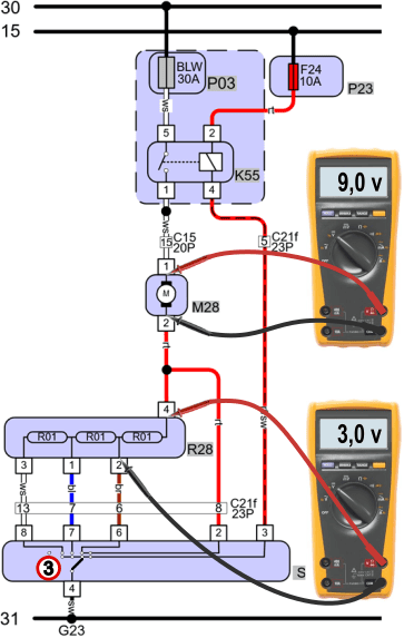
Malfunction 2: the fan runs too slowly in position 1:
When switching on one of the four positions, we may notice that the fan runs more slowly than it should. This can be in position 1 as in this example, but also in position 2. In that case, the fan in position 2 could run just as slowly as in position 1.
We have a contact resistance in the wire between the heater resistor and the switch.
- the voltage difference across the heater motor is 2 volts. In the fault-free situation this was 3 volts, so due to the lower voltage it will run more slowly;
- the voltage difference across the heater resistor is 9 volts, which shows that voltage is being taken up in the resistors, but does not indicate a possible malfunction;
- the voltage difference across the white wire, between pin 3 of the resistor and pin 8 of the switch, is 1 volt. This is a loss as a result of a contact resistance;
- due to the voltage loss in the wire, less voltage remains for the fan motor to operate, causing it to run more slowly;
- conclusion: the white wire is damaged and must be repaired.
Malfunction 3: the fan runs too slowly in all positions:
When the interior fan blows too weakly in all positions, this may indicate a defective fan. In that case, it is best to set it to position 4 to measure the voltage across the fan motor. According to the theory of the V4 measurement, this voltage should be approximately equal to the battery voltage. In the image below we see that the voltage in position 4 is only 7 volts, because there is a 5 volt loss in the ground wire between the switch and the ground point. We also measure these 5 volts when we measure between pin 2 of the motor and G23 (ground). In the image, the relevant wire has already been found.
When there is a contact resistance in a wire and the switch is not in position 4 but in position 3, we are making things unnecessarily complicated. In that case, a resistor is connected in series to make the motor run more slowly. We then have both a contact resistance as a fault and a resistor that we deliberately place in series with the motor to make the fan run more slowly. The last two images show the voltage differences in position 3.
Conclusion: if the motor runs too slowly in all positions, set it to the highest position (so that the heater resistor is not in series) and perform the V4 measurement across the battery (V1) and the fan motor (V2), followed by V3 and V4 if V2 differs by more than 0.5 volts from V1. Read all about this at: meten met de multimeter.


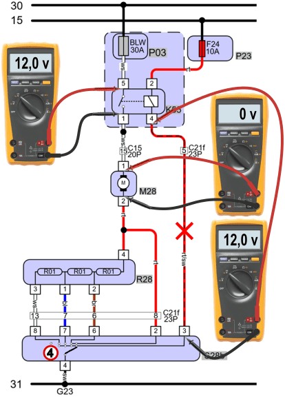
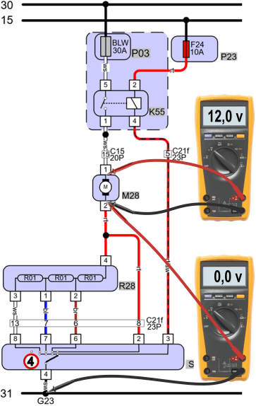
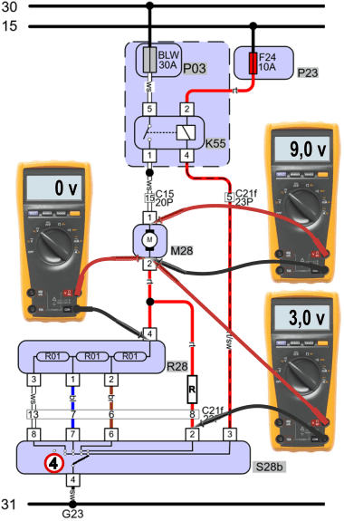
Malfunction 4: fan does not work in position 3, in other positions it works properly.
The complaint is similar to malfunction 1, but in this case there is a broken wire between the heater resistor and the switch. With a V4 measurement we make the voltage differences clear. Because the V4 measurement is considered known, the V1 and V3 measurements are omitted.
- the voltage difference across the motor (V2) is 0 volts;
- the difference across ground (pin 2 of the motor relative to a ground point) is 12 volts, which points to an interruption;
- the measurement between pin 2 (resistor) and 6 (switch) shows a 12 volt difference. This wire is interrupted;
- conclusion: the brown wire between pin 2 and 6 is interrupted and must be repaired.
Malfunction 5: fan runs properly in positions 1, 2 and 3, but in position 4 it runs just as fast as in position 3.
No difference in operation is noticed between positions 3 and 4. Whereas in position 3 a voltage of 3 volts was taken up in the resistor, this 3 volts is now taken up in the contact resistance between the fan motor and the switch. The complaint does give us insight into the location of the resistance: because the fault is not present in other switch positions, we know for sure that the fault is located after the junction point.
Conclusion: the wire between the junction point and the switch is damaged and must be repaired.
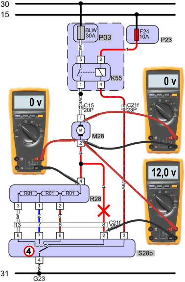
Malfunction 6: position 4 no longer works.
In positions 1 to 3 the fan motor works properly. A V4 measurement makes it clear that in position 4: V2 is 0 volts and V4 is 12 volts, so we have a voltage difference of 12 volts in the ground, which means an interruption. Between pin 2 of the motor and pin 2 of the switch we measure 12 volts. That is where the interruption is found.
Just like with the contact resistance in malfunction 5, the interruption must be just to the right of the junction point, because the fan works properly in the other positions.
Malfunction 7: interior fan no longer works.
When the interior fan no longer does anything, we first check the voltage differences using the V4 measurement in position 4. The following voltages are measured:
- V1 (battery): 12 volts
- V2 (fan motor): 0 volts
- V3 (loss +): 12 volts
- V4: (loss -): 0 volts
Based on these values, we can draw an interim conclusion that there is an interruption between the positive terminal of the battery and pin 1 of the motor.
A measurement across the relay (pin 5 relative to pin 1) shows a value of 12 volts. The relay contact is open and this is the “cause” of the result of the V4 measurement. The relay does not pass the supply voltage on to the motor and this is in fact the interruption.
Measurements on the control side must clarify whether or not the relay is being actuated. To allow a control current to flow through the coil between pin 2 and 4, pin 4 must be switched to ground by the switch. In a properly functioning situation the voltage difference between pin 4 and a ground point should be approximately 0 volts.
In this situation, a voltage difference of 12 volts is measured across the control wire of the relay. As a result, the relay cannot be operated by the switch and it does not pass the voltage and current on to the fan motor.
Conclusion: control wire between pin 4 of the relay and pin 3 of the switch interrupted.