Hydraulic cylinder:
A hydraulic cylinder consists of a housing containing a piston and piston rod. Its operation is based on Pascal’s law as previously described. The hydraulic fluid is pumped into the cylinder on one side, causing the piston to make a linear movement. Very high forces can be transmitted with the hydraulic cylinder. The following image shows the three situations of a double-acting cylinder:
- A: the piston with piston rod is in the leftmost position.
- B: hydraulic fluid is supplied through the left port of the cylinder. The fluid pushes the piston to the right. The fluid on the right-hand side of the piston is discharged from the cylinder through the right port.
- C: the piston is in the rightmost position.
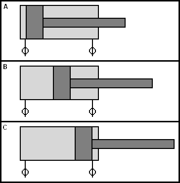
On the piston-rod side (on the right in the image above) the surface area where the hydraulic fluid presses against the piston is smaller.
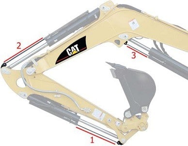
The following image shows the mechanism of an excavator. The combination of hinges, levers and individually controlled hydraulic cylinders ensures that the bucket is highly manoeuvrable. The cylinders are of the double-acting type: by changing the direction of the fluid to and from the cylinder, the piston moves in the opposite direction.
In addition to double-acting cylinders, there are also:
- Single-acting cylinder: this type of cylinder has one hydraulic port. A spring behind the piston provides the return stroke.
- Cylinder with hydraulic cushioning: in this case the piston movement is decelerated at the end of the stroke.
- Telescopic cylinder: a number of nested cylinders provide a large working length when extended. When retracted, the installation space is relatively small thanks to the telescopic design.
Calculating stroke volume:
Due to the different cylinder designs, their applications are versatile: when the piston rod has to exert a lot of force, the diameter of the piston rod is larger, as is the piston, the cylinder and the fluid volume in the cylinder. The dimensions depend on the installation location and the application for which the cylinder is used. We encounter the following dimensions:
- piston diameter (D)
- rod diameter (d)
- piston stroke (s)
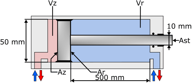
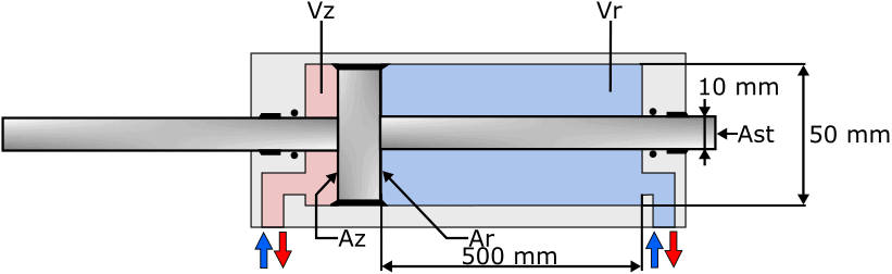
The image below shows a cylinder with the piston and piston rod inside it. The explanation of the abbreviations is shown next to the image.
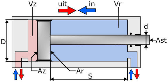
Explanation:
- D = piston diameter
- d = rod diameter
- s = stroke
- Az = piston area
- Ar = annular area
- Ast = rod area
- Vz = volume piston side
- Vr = volume rod side
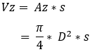
With the dimensions of the piston and cylinder we can calculate the stroke volume on the piston side (Vz). For this we need the piston area (Az) and multiply this value by the stroke. When Az is unknown, we can calculate the area with the following formula:
To determine the stroke volume on the right-hand side of the piston, we must subtract the area of the piston rod from it. This gives the following formula:
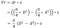
We will use these formulas to calculate the stroke volume of the cylinder shown below.
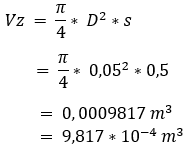
We enter the data for calculating the stroke volume on the piston side in the fully extended position into the formula. The final answer is in cubic metres because it concerns a volume. We then convert the final answer into scientific notation.
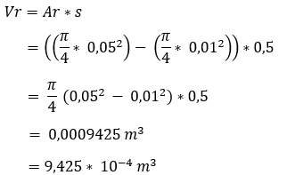
Next we enter the data on the rod side to calculate the fluid volume there with the piston fully retracted. We arrive at a lower fluid volume because this space is occupied by the piston rod. We also convert this answer into scientific notation.
For cylinders with a through piston rod of equal diameters, determining the fluid flow is easier: the incoming volume flow is equal to the outgoing volume flow.
Calculating system pressure:
The pressure in the cylinder that pushes the piston to the right acts on the piston area Az. We can calculate this pressure if the force exerted by the piston on the object to be moved is known. This force is 10 kN (10,000 N). For convenience we use the other data of the piston and cylinder from the previous paragraph.
We calculate the pressure in the cylinder with the following formula. The force F is known (10,000 N), but the piston area is still unknown.
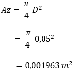
So we first calculate the piston area:
Now that we know the piston area, we can calculate the pressure:
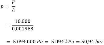
By dividing F (newton) by A (square metre) we obtain an answer in newton per square metre [N/m²]. This is equal to pascal, because 1 Pa = 1 N/m².
By dividing the number of pascals by 100,000 we obtain the number of bar. We can see this in the answer of the formula above.
Calculating volume flow:
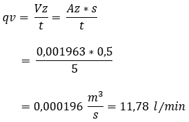
We can calculate the volume flow by dividing the known values by the time in which the piston makes the full stroke (s). We set this time (t) at 5 seconds.
We calculate the volume flow using the following formula:
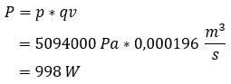
Calculating power:
Finally, we can calculate the required power to move the cylinder from left to right. To do this, we multiply the system pressure by the volume flow. The calculation is shown below.
Related page: