Introduction:
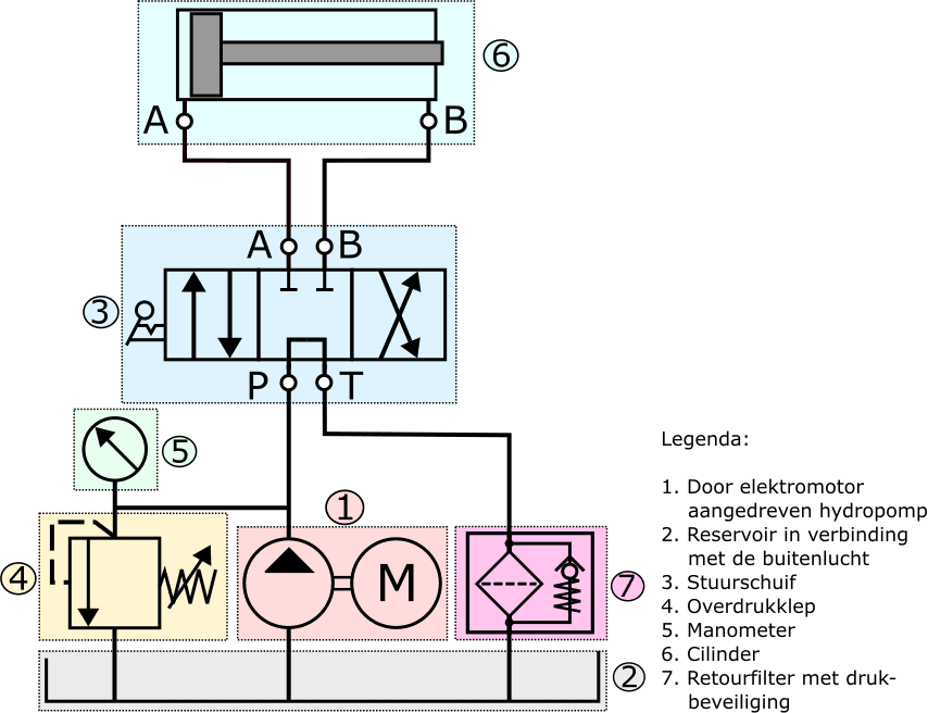
The hydraulic pump (1) draws oil from the reservoir (2) and pumps the oil into the system. After the oil enters the return line via the control valve, the relief valve or the cylinder, the oil flows back to the reservoir without pressure.
The hydraulic pump in the image is driven by an electric motor, which supplies mechanical power in the form of torque and speed. The hydraulic pump converts this into hydraulic power. The pump output / flow rate depends on the speed and the displacement of the hydraulic pump.
Hydraulic pumps almost all operate according to the positive displacement principle. The designs can be divided into:
- gear pumps;
- vane pumps;
- piston pumps.
The following paragraphs go into this in more detail.
Gear pump:
The gear pump is used in hydraulic systems with a low working pressure of up to 140 to 180 bar. Because of its simplicity, low cost price and reliable characteristics, the gear pump is one of the most commonly used hydraulic pumps in hydraulic applications.
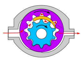
In the gear pump with external gearing there are two gears that rotate in opposite directions. One of the gears is driven externally and in turn drives the other gear.
- suction side: the teeth move apart on the left-hand side. Due to the increase in volume in the cavities, a vacuum of approx. 0.1 to 0.2 bar is created, causing oil to be drawn in. The gears transport the oil along their outer circumference to the pressure side;
- pressure side: here the teeth mesh. The oil in the pressure line is displaced into the system.
The pressure on the pressure side depends on the resistance the oil encounters in the hydraulic circuit.
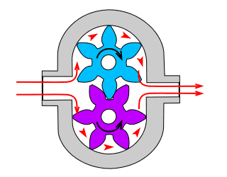
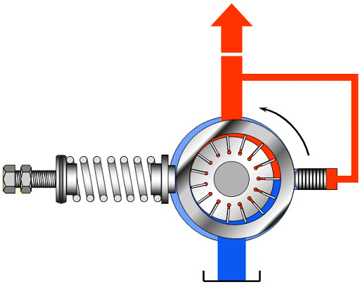
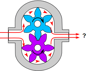
The gear pump with internal gearing contains a crescent-shaped insert. The inner (blue) gear is driven externally and thereby drives the outer (purple) ring with internal gearing in the indicated direction of rotation. Just as with the pump with external gearing, a vacuum is created as soon as the space between the teeth increases. The pump thus draws oil from the reservoir. When the gears mesh, the oil is displaced into the system. The crescent-shaped insert provides a separation between the suction and pressure sides.
With this type of hydraulic pump a pressure of up to 300 bar can be achieved. The pump has a uniform output and produces very little noise.
Gear pumps always have a fixed displacement. With a constant drive speed, the output is constant. At the outer circumference of the gears, the tooth tips run very close to the pump housing and provide the radial sealing. In the middle of the pump, where the gears mesh, there is also some sealing between the tooth flanks and the wear plate. There will always be a small amount of oil leaking away between the sealing surfaces.
We find the gear pump in the following fields of application:
- vehicle technology (including automatic transmission);
- mechanical engineering;
- agricultural hydraulics;
- aircraft hydraulics.
Vane pump:
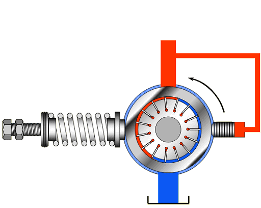
The vane pump has a rotor with radially mounted vanes. On the suction side (blue) the volume increases, creating a vacuum and drawing in oil. On the pressure side (red) the volume decreases, pressure is created and the oil is forced into the line.
The rotor is mounted eccentrically to the stroke ring, which makes the output adjustable:
- In the image below we see on the left a pump where the output is 0 cm³ per revolution. The pump no longer delivers oil then;
- The right-hand image shows the adjusted stroke ring, which results in maximum output.
We find the vane pump in the following fields of application:
- agricultural and road construction machinery;
- machine tools;
- aviation hydraulics;
- mobile hydraulics.
Piston pump:
The axial piston pump is used in systems that operate at higher pressures (>250 bar) and transmit greater power, because the efficiency of this type of hydraulic pump is high. We distinguish between radial and axial piston pumps.
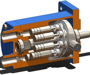
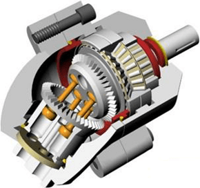
Axial piston pump:
The input shaft of the axial piston pump drives a swash plate. The swash plate is set at a certain angle and converts the rotary motion of the input shaft into a reciprocating motion of the pistons. The pump is equipped with suction ports and discharge valves, so the direction of rotation of the input shaft has no influence on the flow direction of the hydraulic oil.
By adjusting the angle of the swash plate, the stroke of the pistons can be varied. The steeper the angle of the swash plate, the greater the stroke of the pistons and the more oil is displaced. We encounter this technology in air conditioning compressors.
The images below show the axial piston pump.
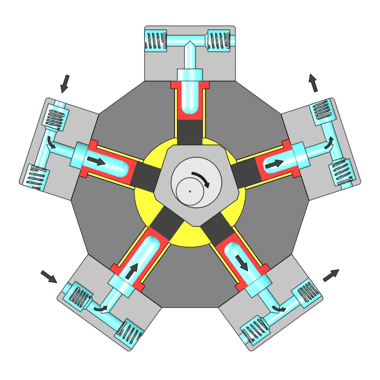
Radial piston pump:
Radial piston pumps are mainly found in heavy-duty drives in ships, such as dredging installations, winch drives and rudder systems, and in mechanical engineering. These pumps have a short installation length, are suitable for high working pressures (700 bar) and deliver high torque at low speed.
The radial piston pump in the next image contains five radially mounted pistons in a star shape around the drive shaft. Because the ring is made eccentric, a radial piston movement is created. A distributor plate rotating with the drive shaft ensures that each cylinder is connected to the suction or pressure line at the right moment.
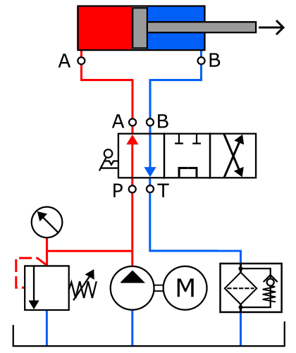
Introduction calculation examples hydraulic pump:
In order to move the piston with the correct force and speed, the hydraulic pump must supply sufficient pressure and a fluid flow that is large enough. The greater the load that the cylinder has to handle, the higher the requirements placed on the hydraulic pump.
Below are three paragraphs in which we will calculate the flow rate, the required pressure, and the required power, taking efficiency into account, of the hydraulic pump in the accompanying diagram.
- pump displacement (V) = 15 cm³ / rev;
- pump speed (n) = 1200 rpm;
- system pressure: 50 bar.
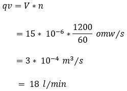
Calculating hydraulic pump flow rate:
The amount of hydraulic oil displaced by a hydraulic pump depends on the speed and the displacement of the pump. The data are listed in the paragraph above.
In the formula we convert the speed per minute to seconds by dividing the value by 60. In the final step we convert cubic meters per second to liters per minute by multiplying the answer by 60,000.
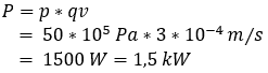
Calculating required power of the hydraulic pump:
The hydraulic pump must deliver hydraulic power to transport fluid to the cylinder and set the piston in motion.
Using the data from the paragraph “Introduction calculation examples hydraulic pump” and the answer from the previous paragraph, we can calculate the required power of the hydraulic pump. For clarity, they are listed again here:
- pump displacement (V) = 15 cm³ / rev;
- pump speed (n) = 1200 rpm;
- system pressure: 50 bar;
- flow rate: 18 liters per minute.
We convert the system pressure of 50 bar to Pascal and the flow rate to cubic meters per second. We write this in scientific notation.
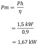
Calculating required power of the drive motor:
The pump shaft (input shaft) delivers the mechanical power, which usually comes from an electric motor or combustion engine. The hydraulic motor converts the mechanical power into hydraulic power. When converting energy, losses will always occur. The drive motor must therefore supply more power in order for the hydraulic pump to deliver its required power.
In this example we assume an efficiency of 90%.
Related page: