Introduction to hydraulics:
Hydraulics is understood to mean the transfer of energy (forces and movements) by means of a fluid. The word “hydraulics” comes from Greek (hydro = water, aulos = pipe). Hydraulics is a drive, control and regulation technology that we encounter in automotive engineering, mechanical engineering, drive and control technology, aviation and agriculture. We can distinguish hydraulics into hydrokinetic and hydrostatic drive:
- Hydrokinetic: high fluid velocities and relatively low pressures, such as the torque converter in the automatic transmission;
- Hydrostatic: low fluid velocities and high pressures, as we find in power steering.
In practice, in addition to hydraulics we also find pneumatics, electronics and mechanical drive technology. Each technology has its own advantages and disadvantages for the application in which it is used. The advantages and disadvantages of hydraulics compared to the other technologies are:
Advantages:
- High power density; large forces and torques can be transmitted with small component dimensions;
- Continuously variable speed, force and torque control;
- Hydraulic energy can be stored and reused;
- High accuracy and constant positioning are possible.
Disadvantages:
- Relatively expensive technology;
- Sensitive to contamination;
- Possibility of leakage (both internal and external).
In a hydraulic system a displacement of fluid takes place. The fluid flow can be set in motion by means of a pump or a piston. All hydraulic systems are based on Pascal’s law:
“pressure exerted on a fluid at rest in a confined space is transmitted undiminished in all directions”.
We see this principle in the following image, where a force (F1) is exerted on the piston surface with a piston. The force causes a pressure in the fluid-filled (closed) system, which pushes the piston upwards with force F2.
The pressure depends on the force and the surface area of the piston. On the page “pressure in the hydraulic system” this is explained by means of animations and calculations.
Hydraulic diagrams:
The hydraulic diagrams, made up of symbols, are compiled by the manufacturer so that during maintenance and / or repair work it is possible to see how components are connected. The flow diagram also shows which types of components are present in the system. An overview with the symbols can be found on the page with the hydraulic symbol list.
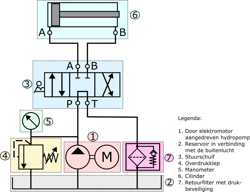
In the following image we see the most commonly used components in a hydraulic system. The components are shown with a colour and a number.
An electric motor provides the drive for the hydraulic pump (1), which transfers the hydraulic oil to the directional control valve (4).
The pressure relief valve (2) protects the system against excessively high pressures. The system pressure can be read from the pressure gauge (3).
The manually operated directional control valve has four connections:
P (pump), T (tank), and the connections A and B for the cylinder.
The directional control valve can be set in three positions:
- at rest (current position);
- to the right;
- to the left.
Depending on the position of the directional control valve, the cylinder is supplied with hydraulic oil and the piston will move.
The following images outline the different positions of the directional control valve with which the cylinder can be moved.
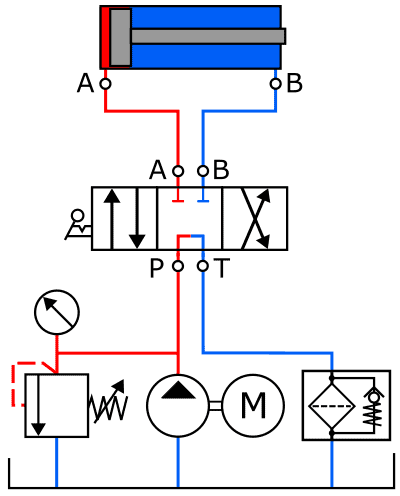
1. Directional control valve in neutral position:
The hydraulic pump in the following diagram is again driven by an electric motor. The pump draws the hydraulic oil from the reservoir and feeds the oil under increased pressure to the pressure relief valve, the pressure gauge and the directional control valve.
The directional control valve is in the middle position, causing the P and T ports to be interconnected and the hydraulic oil to enter the directional control valve via P and leave it via T.
From port T the hydraulic oil flows via the return filter to the reservoir. A pressure protection device is located in the housing of the return filter, which opens against the spring force when the fluid pressure rises.
The increase in pressure can occur when the filter becomes clogged by dirt particles.
Because the hydraulic oil circulates in this position of the directional control valve, hardly any pressure builds up. There is only a certain degree of resistance that the oil experiences in the directional control valve, the lines and the return filter. However, this resistance is so low that the oil is circulated virtually without pressure.
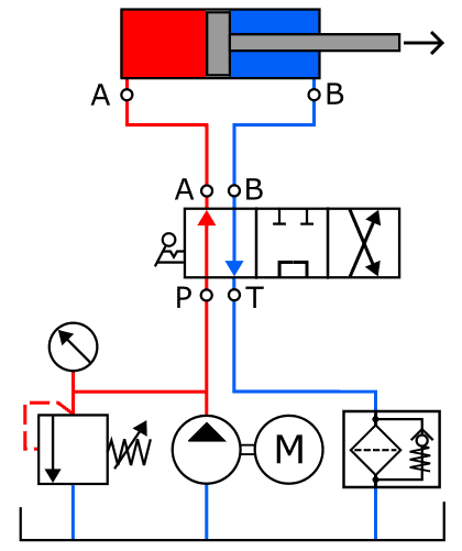
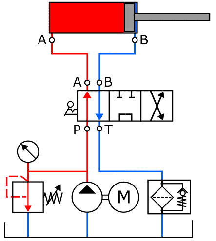
2. Directional control valve in left position:
The directional control valve is set to the left position. The ports P and A, as well as T and B, are interconnected in this position. The hydraulic oil moves via the lines to the left side of the cylinder. The pressure build-up on the left side of the piston begins and is now actuated.
Because the return (B) of the cylinder is now connected to the T port of the directional control valve, the oil on the right-hand side in the cylinder can flow to the reservoir via the return filter.
The cylinder makes an outward movement until the end stop is reached. We see this in the next situation.
3. Piston in end position:
In this situation the piston is fully extended, so the end stop has been reached. The overpressure protection prevents the pressure from rising too high. Without this protection the pressure would rise uncontrollably, resulting in damage.
The pressure control valve (in the image it is shown to the left of the hydraulic pump) opens when the preset pressure is reached. The pressure relief valve connects the supply line from the hydraulic pump to the return line. There is now a constant circulation via this pressure relief valve until the pressure decreases.
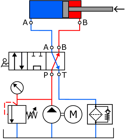
4. Directional control valve in the right position:
The directional control valve is now operated in the right (opposite) position. Compared to situation 2, the lines are cross-connected: P is now connected to B, causing the pressure build-up to take place on the right-hand side of the piston. Port A is connected to T (return). In this position of the directional control valve the piston moves to the left.
The pressure build-up will again increase when the end stop of the piston is reached, up to the pressure at which the pressure relief valve opens. The directional control valve must then be set back to the middle position.
Related page: