Introduction to the MAP sensor:
The intake manifold of an engine can be fitted with a “Manifold Air Pressure sensor”, abbreviated as MAP sensor. This pressure sensor measures the absolute pressure in the intake manifold. The sensor can be mounted on the intake manifold or connected externally by means of a small hose. The vacuum or overpressure is converted by the sensor into a signal voltage that is derived from the supply voltage. This makes the MAP sensor an active sensor. The measuring range is often from 20 – 300 kPa (0.5 to 3 bar). We distinguish between the MAP sensor for a naturally aspirated engine and a boost pressure sensor for an engine with boost control.
MAP sensors are used to measure engine load. The manifold (under)pressure is a measure of the volumetric efficiency. The fuel injection, among other things, is determined from the value recorded by the MAP sensor.
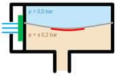
Inside the MAP sensor, two air chambers are separated from each other by a diaphragm. The pressure in the MAP sensor causes the diaphragm in the sensor to deflect. In the illustration, the ambient air pressure is present in the upper part and the vacuum in the lower part. Several strain gauges are applied to this diaphragm that register the deflection of the diaphragm. A greater pressure difference causes the diaphragm to bend further.
The MAP sensor consists of – usually – four piezoresistive strain gauges mounted on a diaphragm in a Wheatstone configuration. When the material is compressed or stretched, the resistance value of the strain gauges changes. In the Wheatstone bridge, the change in resistance is converted into a change in voltage. This forms the signal voltage, which is sent to the ECU. In the ECU there is an A/D converter that digitizes the voltage signal before it reaches the microprocessor.
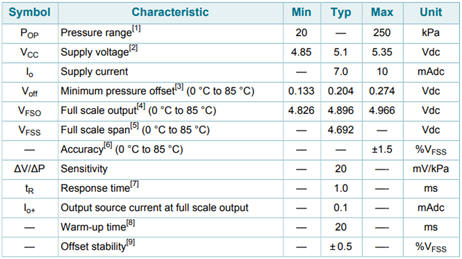
Properties of the MPX4250AP:
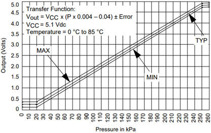
The level of the output voltage therefore depends on the pressure in the intake manifold and ranges between 0.1 and 4.9 volts. In the image below, the characteristic of a commonly used MAP sensor of the type MPX4250AP is shown. The line is linear. At an ambient air pressure of 100 kPa (which is equal to 1 bar) the sensor outputs a voltage of approximately 1.8 volts at an average operating temperature (TYP).
The characteristic shows that the sensor does not register anything at p ≥0, ≤20. This means that with the throttle valve fully open and under high load, the engine no longer relies on the value from the MAP sensor, but switches in software to a substitute value. The recorded throttle opening angle is then used instead.
The component properties of the MPX4250AP are shown in the table.
Signal voltage of a naturally aspirated engine:
The signal voltage of the MPX4250AP sensor in a naturally aspirated engine can look as follows. In this graph the throttle is alternately opened, released, accelerated and decelerated.
Boost pressure sensor:
Internal combustion engines with forced induction are equipped with a boost pressure sensor to measure the pressure in the intake tract. This sensor is located in the air hose (or pipe) between the intercooler and the engine’s throttle body. The boost pressure can be achieved in the following ways:
- diesel engines: exhaust gas turbocharger;
- petrol engines: exhaust gas turbocharger or mechanical supercharger, or a combination of these.
The boost pressure sensor (also called turbo pressure sensor or boost sensor) is in fact a MAP sensor with a larger measuring range than that of a naturally aspirated engine:
- naturally aspirated engine: up to 1.5 bar;
- forced-induction engine: up to 2.5 bar;
- forced-induction engine: up to 3.5 bar.
The engine management system translates the voltage signal from the pressure sensor into a pressure value and uses this to control the turbo’s wastegate. When a turbo is equipped with VGT, the position of the vanes is adjusted.
- During acceleration, the turbo must provide more pressure. The wastegate remains closed until the desired intake air pressure or boost pressure is reached.
- When the desired boost pressure is reached, the ECU actuates the wastegate, which will open partially. The pressure is kept constant or reduced by opening the wastegate further.
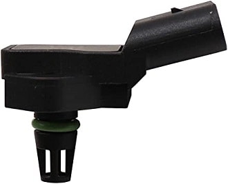
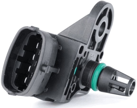
Combination with temperature sensor:
MAP sensors can be housed together with the intake air temperature sensor in a single unit. This can be recognized by four terminals. The temperature is also an important factor in determining the injection quantity.
From the intake air temperature we can determine the following:
- With a cold engine, the intake air temperature must not differ by more than 5 degrees from the coolant temperature;
- Intake air temperature higher than coolant temperature: EGR valve remains open.
In case of deviations from the two points above, the ECU can generate a fault code.
Diagnosing the boost pressure sensor:
Malfunctions in the boost pressure sensor can be recognized by the following symptoms:
- Reduced engine power;
- Inconsistent pulling power during acceleration;
- Excessive fuel consumption and emissions;
- Malfunction indicator lamp (MIL) with related fault codes (DTCs).
With the above complaints it is of course obvious to read out the fault memory of the engine electronics. In the event that the engine management system stores a fault code relating to an incorrect signal from the boost pressure sensor, we can expect the following codes: P0105, P0106, P0107, P0235, P0236, P0238.
Causes of an incorrect signal may include:
- Internal wear, contamination or even blockage of the sensor element;
- Excessive contamination in the intake duct, e.g. due to carbon deposits in the intake manifold or intake ports of the cylinder head;
- Exhaust blockages;
- Leaks in the air hoses;
- Wiring problem between the sensor and ECU.
Contamination in the intake tract can be determined by removing components such as the throttle valve / throttle body and the intake manifold, or by inspecting the inside of the manifold with an endoscope. Exhaust blockages can be caused by a defective catalytic converter core or a clogged particulate filter.
We can investigate problems with the sensor electronics or the wiring between the ECU and the sensor by studying the wiring diagram and taking measurements.
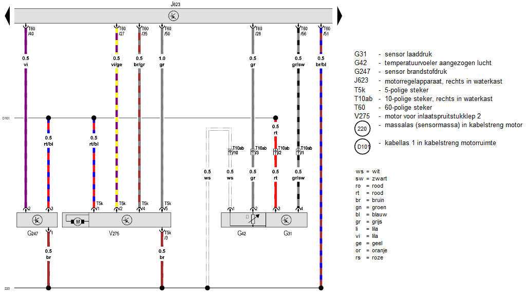
The figure below shows the wiring diagram of a boost pressure sensor. Click here for an explanation on reading wiring diagrams.
The boost pressure sensor and intake air temperature sensor are integrated in one housing. The sensors share a common positive supply (pin 3) and ground (pin 1). From this we can see that it is an active sensor. The signal wire of the boost pressure sensor (pin 4 on the sensor) is grey/black in color and is connected to pin 56 of the engine control unit. In this diagram we cannot determine whether the signal is an analog voltage (AM) or digital (PWM). We can find that out by measuring.
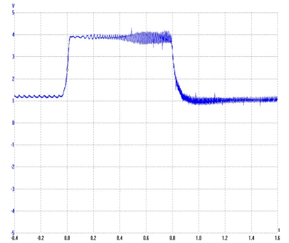
The illustrated boost pressure sensor sends an AM signal (Amplitude Modulation), as can be seen from the oscilloscope trace. The voltage level represents the pressure variation over time. The following screenshot shows the voltage curve of a boost pressure sensor. The oscilloscope settings are: 1 volt per division and 200 ms per division.
With the engine idling, the turbo does not yet generate boost pressure. The absolute pressure in the intake manifold is approximately 100 kPa. The sensor translates this pressure into a voltage of approximately 1.6 volts.
When the throttle is opened, the engine speed and thus the turbo pressure increase. The pressure gradually rises to 1.4 bar. In the oscilloscope trace, the voltage at that pressure almost reaches 3 volts. After that point, the accelerator pedal is released and the boost pressure drops.
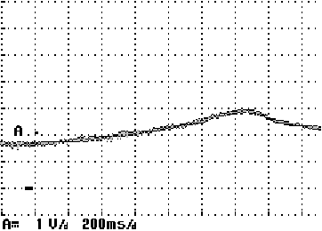
In the event of a defect in the boost pressure sensor or its wiring, irregularities can be observed in the signal. The voltage signal must be between 0.5 and 4.5 volts with a supply voltage of 5 volts. The two images below show a signal with interference (left) and without interference (right).

The page fault-finding in sensor wiring describes measurement techniques for various types of sensors, including this active sensor, along with possible malfunctions and causes.