Final compression pressure:
During the compression stroke the intake and exhaust valves are closed and the piston moves upwards. The air present (or the air/fuel mixture) is therefore compressed. As soon as the piston reaches TDC (top dead centre), the maximum compression pressure is reached. This is called the final compression pressure. As soon as the fuel is supplied to the air present, the spark plug will spark to ignite the mixture. The combustion pushes the piston downwards and turns the crankshaft.
The final compression pressure depends, among other things, on the compression ratio.

Measuring compression:
If the final compression pressure is too low, the maximum possible energy cannot be extracted from the fuel. This results, among other things, in a loss of power. If the final compression pressure of only one cylinder is too low, the engine will shake and vibrate, and in most cases a fault relating to cylinder misfire will be stored.
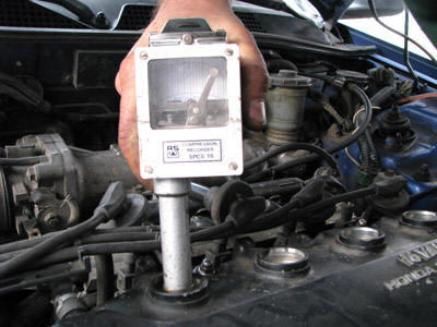
By measuring the compression, the final compression pressure of the engine can be made visible. A self-registering compression gauge records the pressure built up in the cylinder. The technician determines on the basis of this pressure whether the final compression pressure is OK.
Step-by-step plan for measuring compression:
1. Make sure the engine is at operating temperature. The engine components have expanded due to the heat, so the values measured are realistic.
2. Remove the spark plugs.
3. If possible, switch off the fuel supply by disconnecting the injector connectors. The injectors will not be actuated during cranking, so no unburned petrol will end up in the engine.
4. Insert the compression gauge into the spark plug hole. The rubber end of the compression gauge provides the seal between the gauge and the cylinder head.
5. Have someone else crank the engine and fully depress the accelerator pedal. The throttle valve then opens fully, so that the intake air is not restricted.
6. While cranking the engine, press the compression gauge firmly against the cylinder head. Hissing sounds indicate that air is leaking past the compression gauge. The reading on the compression gauge will therefore remain too low.
7. Once the needle of the compression gauge no longer moves further to the right, you can stop cranking. Often 3 to 5 seconds of cranking is sufficient for a good measurement.
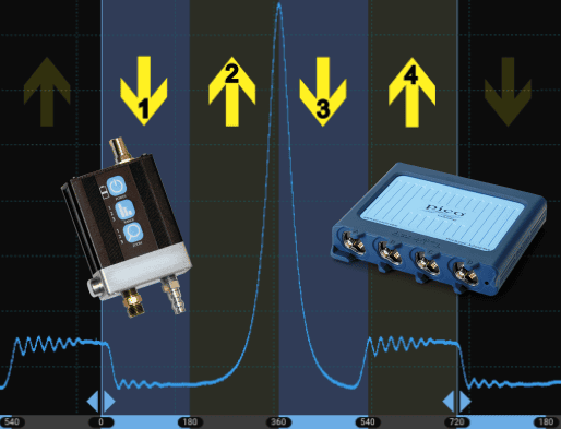
Repeat steps 4 to 7 for each cylinder. When measuring another cylinder, make sure that the measurement is taken on another part of the chart. To do this, press the button on the compression gauge. The chart is pushed upwards. Below are a number of situations that occur in practice:
The final compression pressure of all four cylinders is high enough and no cylinder deviates. The measurement indicates that the final compression pressure of the engine is good.
On cylinder 3 the pressure is lower than on the other cylinders. Insufficient pressure is being built up in cylinder 3. This indicates that there is a problem. This may be, among other things, a problem with the sealing of one or more valves, or a problem with the piston rings.
A deviation in two adjacent cylinders indicates that there is probably a crack in the head gasket or the cylinder head between the two cylinders. During the compression stroke of cylinder 2, air leaks away to cylinder 3 and vice versa.
If the final compression pressure of all cylinders is too low, this can have several causes. These can include worn or sticking piston rings.
The compression test can be used to determine that the final compression pressure is not OK. It is not possible with this test to determine what is causing it. Options for further diagnosis include:
- Pouring a little engine oil into the spark plug hole (not too much!). With worn compression rings, the oil will temporarily provide better sealing. A second measurement will therefore be better, or even OK.
- Removing engine components for a visual inspection.
- Performing a cylinder leakage test.
A modern way of measuring compression is analysing an oscilloscope pattern with a cylinder pressure measurement. In contrast to the (classic) compression test in this paragraph, this does not only measure the final compression pressure but also the pressure during the intake, power and exhaust strokes. This can be done both during cranking and while the engine is running under various conditions. Because the measuring method, the analysis of the pattern and the assessment of the signals are extensive, the cylinder pressure measurement is described on its own page.
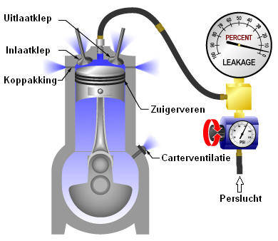
Cylinder leakage test:
With a cylinder leakage test, the cause of the compression loss can be traced. With a cylinder leakage test, compressed air is used to apply pressure to the cylinder space. A pressure gauge is connected to the leakage tester that indicates the leakage in percent. When leakage is present, the pressure gauge will show a value greater than 0%. If the air pressure in the combustion chamber remains constant, the gauge will indicate 0%. Make sure during this measurement that the valves are closed; therefore perform the measurement when the piston is at TDC and in the compression stroke. When the piston is almost at the top but in the exhaust or intake stroke, the valve is often already slightly open due to valve overlap. There will then be leakage past the valve, but this is not a defect but a characteristic. If necessary, remove the valve cover to see whether the camshaft lobes are pointing upwards.
Step-by-step plan for the cylinder leakage test:
- Make sure the engine is at operating temperature. The engine components have expanded due to the heat, so the values measured are realistic.
- Place the piston of the cylinder to be tested at TDC. Make sure the engine is in the compression stroke so that the valves are closed.
- Apply the handbrake and put the car in gear. This prevents the air pressure from pushing the piston down. The car must therefore not be on a lift.
- Connect the compressed air to the cylinder.
- Read the gauge.
If the gauge indicates 0%, there is no leakage. Connect the leakage tester to the next cylinder. If the gauge does show a value, there is leakage. Because compressed air is applied to the cylinder, air will leak out somewhere. Some possibilities are:
- Blowing sound in the intake duct of the air filter: intake valve leaking
- Blowing sound in the exhaust: exhaust valve leaking.
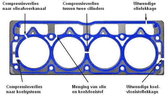
- Blowing sound after removing the oil filler cap: air leakage to the oil sump; this may be caused by a defective head gasket or worn piston rings.
- Blowing sound at cylinder 3 while compressed air is applied to cylinder 2; the head gasket between cylinders 2 and 3 is cracked.
- Air bubbles in the cooling system: head gasket or cylinder head cracked.
Relative compression test with the oscilloscope:
The compression test can also be displayed graphically with the oscilloscope. In that case, no engine components (such as spark plugs) need to be removed. The compression is measured based on the current draw of the starter motor. The measurement is performed while cranking the engine, so you must ensure that the engine does not start. By disconnecting the injector connectors, no fuel will be injected, so the engine will not start. Make sure not to only disable the ignition! If, on a petrol engine, only the ignition coils are disconnected, the engine will continue to inject fuel and the fuel will end up directly in the exhaust.
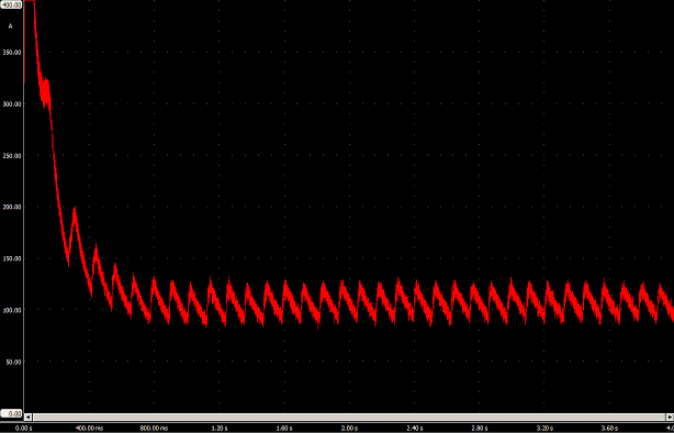
This scope pattern is from a relative compression test carried out on a three-cylinder engine.
The current is shown relative to time. The measurement was carried out by connecting the current clamp to the ground cable from the body to the battery and measuring the current drawn while cranking. Each compression stroke causes the starter motor to have to “work harder” to turn. During the compression stroke, the starter motor will therefore need more current to turn. This can be seen in the peaks of the scope pattern. When no deviation can be seen in the peaks, the result of the relative compression test is acceptable.
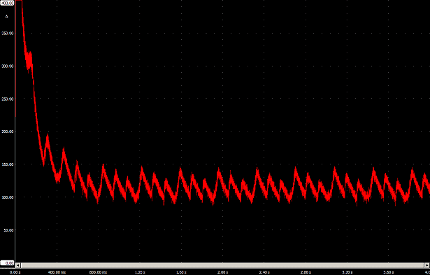
The scope pattern shown is from a three-cylinder engine in which one cylinder has no compression. Compared to the above scope pattern, you can see that one peak is missing. The pattern shows compression loss. There is one high peak (cylinder 3), one low peak (cylinder 2) and one peak in between high and low (cylinder 1). The lowest peak (from cylinder 2) indicates that this cylinder has a final compression pressure that is too low. For that compression stroke the starter motor has to do less work to rotate the crankshaft. The medium peak is also caused by that cylinder where compression loss is present, but this does not necessarily mean that there is compression loss in this cylinder as well. This is explained below using the drawing:
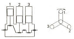
Because the firing order of cylinders 2 and 1 follow each other (firing order 1-3-2), the compression loss in cylinder 2 also affects the scope pattern of cylinder 1. While the piston of cylinder 2 is moving upwards (and the starter motor has to do less work due to the compression loss), the piston of cylinder 1 also begins to move upwards.
Without compression loss, the crankshaft rotational speed would drop during every compression stroke. However, because the rotational speed at cylinder 2 has not dropped as far, this also affects the crankshaft rotational speed of cylinder 1.
With the scope patterns above, you can see whether the engine is in good condition. If all peaks are of equal height, the relative compression test is OK. In the event of a deviation, these scope patterns cannot be used to determine which cylinder is the cause. To determine this, an ignition measurement can be performed with channel B. This channel can be displayed in the same screen. The scope pattern of the ignition will be located above the line of the compression measurement, allowing the correct cylinder to be identified.
Related pages: