Measuring piston diameter:
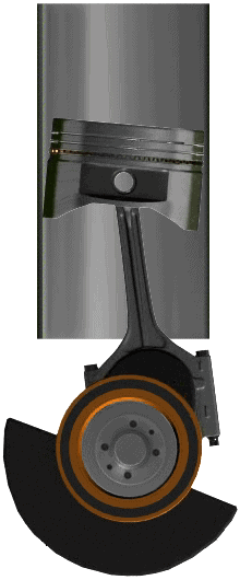
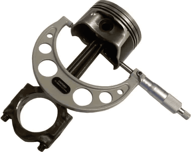
We can determine the diameter of a piston with a micrometer. We place the micrometer at a right angle to the piston pin; at this location the highest forces occur as a result of the side thrust. When the piston wears, the diameter will decrease the most at this point.
The piston size is stated in the manufacturer’s technical data.
Measuring cylinder diameter:
The cylinder diameter can increase due to wear, partly as a result of the side thrust. With the cylinder measurement we can determine whether there is wear and to what extent any wear is within tolerance.
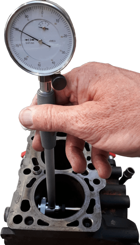
We perform a cylinder measurement with a dial gauge attached to an internal bore gauge.
With a cylinder gauge we can measure the difference in diameter at various points in the cylinder bore. This gives us a wear pattern of the respective cylinder. The diameter can be measured to an accuracy of 0.01 mm.
The cylinder gauge consists of a dial gauge, a connecting rod with a feeler at the lower end, and an interchangeable rod. Depending on the cylinder diameter (bore), this rod must be selected in the correct length. The case usually contains around ten different sizes. If the required size lies exactly between two gauge sizes, a spacer ring can be fitted to the smaller gauge to obtain the desired length.
Example:
The cylinder diameter is 87.00 mm. We choose the rod with a length of 85.00 mm and fit a 3 mm spacer ring to obtain a length of 88.00 mm. The length is now 1 mm more than the cylinder diameter: this is important for this measurement, because in the event of wear the cylinder diameter has become larger. We determine the length of the rod with a micrometer.
To start the measurement, we insert the lower part of the cylinder gauge into the cylinder bore. The following text refers to the measurement in the illustration:
- The right-hand part has a small wheel that is not adjustable in length;
- The left-hand part is the adjustable measuring pin onto which we have mounted a rod of the correct length during setup;
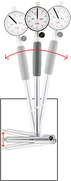
To determine the smallest diameter, the cylinder gauge must be moved back and forth. The pointer in the micrometer moves from left to right. In the illustration three positions are visible: left, centre and right. The centre position is shown in dark grey, the other positions are light-coloured.
- Moving to the left position: the measuring pin springs out of the cylinder gauge. The pointer indicates 0.1 mm movement;
- Moving to the right position: the measuring pin again springs out of the cylinder gauge, and the pointer again indicates 0.1 mm.
- Dial gauge in the middle: here the diameter of the cylinder is smallest. The measuring pin is therefore pressed in to the maximum. The pointer now indicates 0 mm.
The pointer does not necessarily have to indicate 0 mm when the cylinder gauge is in the middle. If you take into account that the zero point is at 50 on the dial (the pointer is rotated 180 degrees compared to the current situation), then the deflection of 0.1 mm will cause a movement between 50 and 60 on the dial; again 0.1 mm.
The above steps must be repeated in several locations. When the dial gauge reads 0 mm in the middle at all locations, there is no wear. However, if the pointer moves past 0, the clearance has become larger. The stroke of the pointer has then increased: for example a total of 1.1 mm instead of 1.0 mm. That means there is wear of 0.1 mm.
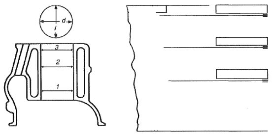
The following illustration shows a cylinder bore with three possible measuring heights: 1, 2 and 3. The measurement must be carried out in both the longitudinal and transverse directions.
The diameter at the top of the cylinder (3) will be the largest: here the forces of the piston against the cylinder wall are minimal. Halfway down the cylinder the force is greatest: in case of wear, this diameter will be the largest.
A tip for this type of measurement is to make a sketch and note the measured values on it. When the diameter is larger than the value specified by the manufacturer, the respective cylinder is rejected.
Piston clearance:
The clearance between the piston and cylinder depends on both the piston diameter and the cylinder diameter:
- piston wear: diameter becomes smaller;
- cylinder wear: diameter becomes larger.
Wear is a result of, among other things, the side thrust that occurs when the piston is pushed downward by the combustion pressure and the crank-connecting rod mechanism. More wear results in a greater distance between the piston and cylinder. The consequence is that the piston has more freedom of movement and begins to “rock”. This causes ticking noises, results in higher oil consumption (the lubricating oil can now easily pass the piston into the combustion chamber) and can only be remedied by extensive repair.
There must always be a certain piston clearance to:
- allow components to expand when heating up;
- maintain space for an oil film.
The maximum clearance between piston and cylinder is stated in the factory data. Therefore always read the values specified by the manufacturer. In general, it applies that an average piston clearance of 0.01 mm per cm of piston diameter is used. For turbo engines this is slightly larger, namely 0.015 mm per cm of diameter. When in this case we have a piston with a diameter of 80.00 mm, the bore of the cylinder will have to be (80.00 + (8 * 0.01 mm) = 80.08 mm.
In case of excessive piston clearance, one must check the factory specifications for possible next steps:
- Boring and honing the cylinders, as well as fitting oversized pistons because of the larger cylinder diameter, is not permitted by all manufacturers. It must also be checked whether such a modification has already been carried out in the past. Some manufacturers state that a maximum of three oversizes may be fitted;
- If fitting oversized pistons is not permitted, or the costs are too high, it is better to choose to replace the rotating assembly.