Introduction:
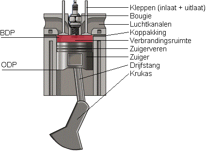
The pistons move up and down in the cylinder. The cylinder is fixed in the engine block and does not move. The piston constantly moves from BDC (Bottom Dead Centre) to TDC (Top Dead Centre) in the cylinder. Combustion takes place at the top of the piston (called the piston crown). When the intake valves open and the piston moves down (BDC), a vacuum is created in the intake section. Because of this vacuum, air (or an air-fuel mixture) is drawn into the cylinder. In a forced induction engine (by means of a turbo or supercharger) the intake air is pushed into the cylinder with a certain boost pressure.
The intake valves close and the piston moves upwards. The air (or air-fuel mixture) is compressed, then ignited in a petrol engine by a spark plug and in a diesel engine by injecting diesel fuel.
As the mixture ignites, the piston is forced down with great force. Then the exhaust valves open and during the upstroke the piston pushes the burnt gases into the exhaust.
Pistons must meet the following requirements:
- An as low as possible mass in order to keep the inertia forces at TDC and BDC as low as possible. Small inertia forces put less load on the bearings and allow higher rotational speeds.
- Good thermal conductivity; the temperature of the piston crown can exceed 400 degrees Celsius. To prevent the temperature of the piston crown from becoming too high, it is constantly cooled with an oil jet directed at the underside. The lower thermal load results in less wear and lower oil consumption.
- Sufficient mechanical strength.
- Low coefficient of friction.
Piston crown:
The top of the piston is called the “crown” or the “piston crown”. Valve reliefs are often machined into the piston crown.
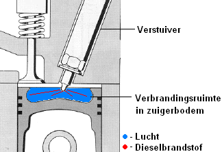
In direct-injection diesel engines, the piston crown often also forms part of the combustion chamber. A special recess is machined in the piston, which serves to create swirl of the air. The air in this recess will make a swirling motion, causing the injected diesel fuel to mix well with this air immediately.
The image shows a direct-injection diesel engine with a pre-swirl chamber in the piston. In an indirect-injection diesel engine, a separate pre-chamber is located in the cylinder head. In that case, there is no combustion chamber in the piston crown.
Materials:
Pistons are usually made of aluminium or magnesium alloys. Sometimes forged aluminium pistons are used whose crowns are chrome-plated. These are very strong and have a low weight. The advantage is that due to their low weight they also exert a lower mechanical load on the cylinder walls (and thus less wear), plus they can therefore be used in very high-performance engines. Because of the specialised production, the price is considerably higher than that of normal aluminium pistons.
Small grooves are also machined into the side of the piston, comparable to the honing grooves in the cylinder wall. These serve to “carry along” the oil during the up-and-down movement. If these small grooves were not present, the oil could simply move past and enter the combustion chamber.
Piston rings:
Piston rings must provide the best possible gas seal between the piston and the cylinder. Leakage past the piston rings causes, among other things:
- Compression loss (and therefore also power loss).
- Oil loss via the combustion chamber.
- Premature ageing and contamination of the oil; as blow-by gases enter the oil, they can mix with it, causing the oil to age.
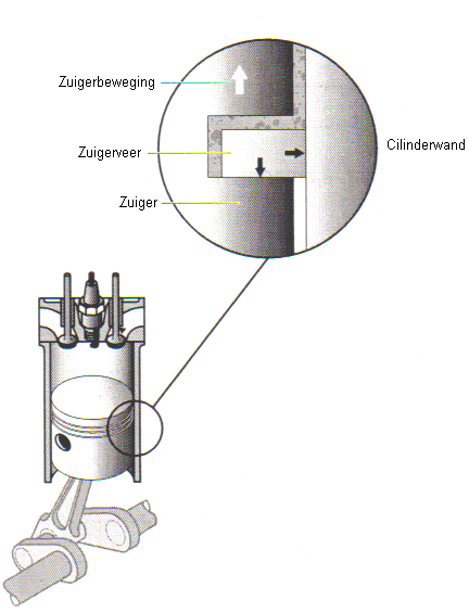
There is always a thin film of oil between the ring grooves and the piston rings (see image below). It is not possible to rely solely on the piston rings to provide sealing. The oil also plays an important role. It works as follows:
- When the piston moves up, the piston rings move to the lower side of the ring groove (see image).
- Oil on the cylinder wall penetrates between the piston ring and the ring groove. This causes the piston to be pressed against the cylinder wall.
When the oil control rings are worn, oil can pass between the cylinder wall and the oil control ring and enter the combustion chamber. The oil is then burnt, resulting in blue or black smoke from the exhaust. Blue smoke is caused by engine oil that enters the exhaust directly, unburnt, and evaporates. With black smoke the oil has taken part in the combustion process, and the burnt oil residues leave the exhaust in the form of (black) soot.
Ring end gap:
The ring end gap is the clearance between the two ends of the piston ring. When the end gap is too small, the piston ring has no room to contract to a smaller diameter. This can damage the cylinder wall and the ring may break. If the end gap is too large, there is too much clearance between the ends; the rings will not seal sufficiently and this can lead to compression loss or increased oil consumption.
The ring end gap is measured with a feeler gauge. In the measurement above, the end gap should be between 0.35 and 0.55 mm. The 0.5 mm feeler gauge could be moved through with slight resistance. The end gap is therefore within specification. For more information, see the page “piston ring measurements” under the heading Mechanical diagnosis.
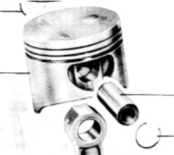
Piston pin:
The piston pin is used to attach the piston pivotably to the connecting rod. The piston pin is (theoretically) mounted in the centre of the piston and secured with a circlip. In reality, the piston pin is mounted off-centre, which benefits performance. More information about this is given below in the next chapter: Piston pin offset.
Piston pin offset:
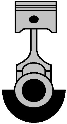
Piston pin offset means that the piston pin is not positioned exactly in the centre (as can be seen in the image). These pistons must of course also be installed in a specific orientation. The orientation is indicated by an arrow marked in the piston crown. This arrow points towards the timing/belt side.
Offsetting the piston pin has an important purpose: to reduce wear on the cylinder wall and to reduce the noise the piston makes when switching from one cylinder wall to the other. As the piston moves up, it is pressed against the left side of the cylinder wall, and as it moves down, against the right side. With every power stroke, the piston would therefore be slammed from the left side against the right side with enormous force.
Because the piston pin is positioned off-centre, the connecting rod is already vertical before TDC. Before the power stroke, the piston already moves towards the right-hand side of the cylinder. When the power stroke now occurs, the piston is already in the correct position and can move straight down in one motion. Due to the offset piston pin, the piston is therefore no longer slammed against the cylinder wall by the power stroke, reducing noise and wear.
Piston deformation:
With a warm engine, the piston takes on a different shape than with a cold engine. The material expands due to the heat. The piston is designed so that expansion takes place in only one direction. Otherwise, the piston could seize in the cylinder.
On the far left of the image, the piston can be seen in its normal state. The middle picture shows the piston in the cylinder seen from above, when it is at operating temperature. The engine has thus been running for some time, so the piston material has warmed up and expanded. The picture on the right shows the piston in a cold state. It is now oval in shape. The arrows at the top and bottom indicate the difference in dimension. The piston in the picture on the right is reinforced in width, and deliberately designed in length so that there is room for expansion. The reason for this is that any material expands when heated. The piston must be given the space to do so.
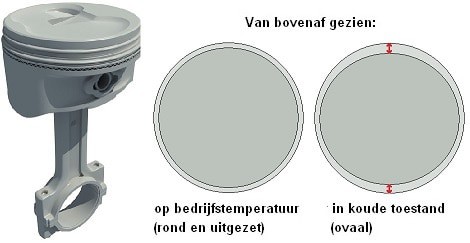
The side that does not expand, that is, in the image the left and right side of the piston, is pressed against the cylinder wall during the power stroke. This side absorbs the side thrust (see the image in the chapter below “piston slap”). It is of course designed this way because otherwise the clearance between the piston and the cylinder wall would be too great under this enormous force. In that case, with a cold engine the piston would be slammed against the cylinder wall and would therefore have a short service life.
Nevertheless, the noise with a cold engine can still be different than with a warm engine. With a cold engine there is still sufficiently more clearance between piston and cylinder that a light ticking noise can be audible. This is not a problem at all, as long as the warm-up phase of the engine proceeds gently. By that I mean that the engine must be brought up to temperature gently (not too high revs and certainly not too much throttle at low revs). If this does happen, the piston has not yet fully expanded and the oil has not yet reached its operating temperature of at least 60 or 80 degrees. The engine will then have a significantly shorter service life. The cylinder wall will wear more quickly, and the side of the piston will also wear heavily. The piston noise can also be reduced by the designer by applying “offset” (see chapter above).
Piston slap:
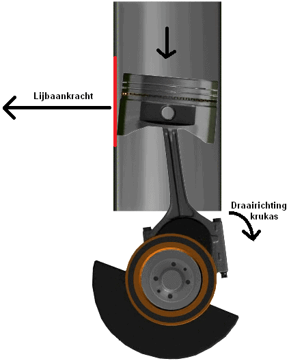
While moving up and down, the piston also moves slightly sideways in the cylinder. When wear occurs in the cylinder wall due to improper use of the engine (think of driving hard / high revs with a cold engine), the (red-marked in the image) part of the cylinder wall can wear into a hollow shape. Poor material choice by the car manufacturer can also play a major role here (think of certain 1.4 16V engines from the V.A.G. group). That means the width of the cylinder increases and the piston therefore gains more freedom of movement due to the side thrust. In that case we speak of “piston slap”. The image shows the piston drawn slightly tilted in the cylinder. The situation is slightly exaggerated, but this illustrates the concept of “piston slap” well.
The result of piston slap is that the engine makes a lot of ticking noises. Sometimes it can almost be compared to the sound produced by a diesel engine. The sound is purely the piston hitting the cylinder wall because of the extra clearance in the cylinder. As a result, oil consumption often increases (due to poor sealing) and wear also tends to increase. The only remedy is to overhaul the engine.
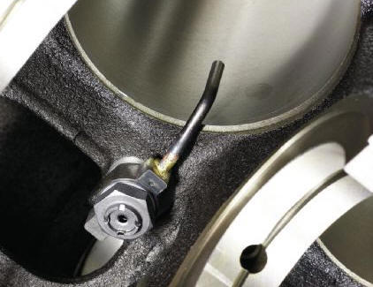
Cooling:
The piston is cooled by motor oil being sprayed against its underside. This can be done with an oil spray nozzle (see image below), or via a drilling in the connecting rod. This, along with more information about cooling and lubrication, is described on the page lubrication system.