Introduction:
Every combustion engine contains valves. There is always at least one intake and one exhaust valve. These valves are driven by one or more camshafts via the timing drive and ensure that fresh air can flow into the combustion chamber, that the air is then trapped during compression, and can then leave the combustion chamber again. The flow of the intake and exhaust gases must occur with as little resistance as possible.
The materials are shaped as effectively as possible for that purpose.
The valves are mounted in the cylinder head. The intake valve is often larger than the exhaust valve, because as much mixture as possible must enter the cylinder. The exhaust valve can be smaller, because the burnt exhaust gases will leave the cylinder anyway during the exhaust stroke, when the piston pushes the gases out of the cylinder.
As an example, we will look at the four-stroke process of a petrol engine. During the intake stroke of the engine, the intake valve opens and, in an indirectly injected petrol engine, an air-fuel mixture is drawn in, and in a directly injected petrol engine only fresh air is drawn in. The air is drawn in because the piston moves downward. The air flowing in occupies the space that becomes available. When the piston moves back up, the intake valve will close. The mixture of fuel and air can no longer escape and is compressed. This is called the compression stroke. That is why it is important that the valves seal properly. The mixture is ignited when the spark plug produces a spark. The piston is then pushed down with considerable force. This is called the power stroke.
During the exhaust stroke the exhaust valve opens and the piston moves upward. The burnt gases now leave the cylinder and go to the exhaust. When the piston is at the top, the exhaust valve closes and the intake valve opens. The piston moves down again and the intake stroke follows. In reality, the intake valve opens slightly earlier, so that the intake and exhaust valves are open at the same time for a short period. This is called “valve overlap”. The speed of the burnt gases leaving the cylinder past the exhaust valve causes a vacuum, which draws in the intake air more strongly. In this way more air can flow into the cylinder than if only the intake valve were to open and the piston were to move downward. The volumetric efficiency is improved this way.
For a more extensive explanation of the four-stroke process, see the page “Werking benzinemotor“.
Material:
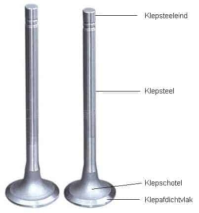
Valves are heavily loaded. Especially the exhaust valves, because they become extremely hot and can only be cooled to a limited extent. The intake valves are partly cooled by the cold air being drawn into the cylinder. The burnt exhaust gases with a temperature of up to 900 degrees Celsius flow past the exhaust valves. That is why exhaust valves are made of a different material than intake valves. Intake valves are often made of chrome-nickel steel. Exhaust valves are often made of chrome-silicon steel. To limit wear caused by the high-temperature conditions, the outer edges of the valve head (the sealing surface) and the valve stems are armoured with a layer of hard metal alloy (stellite). The valves dissipate the largest portion of the heat via the valve head and the valve stem. Sodium-filled valves have even better heat dissipation.
Sodium-filled valves:
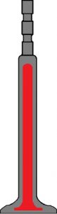
Exhaust valves are hollow on the inside. The hollow space is filled for about 60% with sodium. Sodium is a metal that becomes liquid at a high temperature (from approx. 100 degrees Celsius). In a running engine the valve moves up and down frequently. The sodium in the valve is constantly being sloshed back and forth and thereby transports the heat. The sodium absorbs the heat from the valve head and transfers it to the valve stem. Compared to non-sodium-filled valves, sodium-filled valves can achieve a temperature drop of 80 to 100 degrees.
Intake valves do not need this, because they are already cooled by the incoming air.
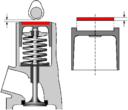
In the image, the grey surface represents the material and the red section the hollow space that is filled with sodium.
Valve guides:
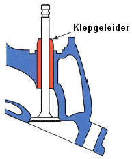
The valves move up and down in the cylinder head. There must be a good seal between the valve and the cylinder head, so that no oil from the cylinder head can run along the valve stem into an intake or exhaust port. There is always a thin oil film between the valve and the valve guide to provide lubrication. In the image, the valve guide is shown in orange.
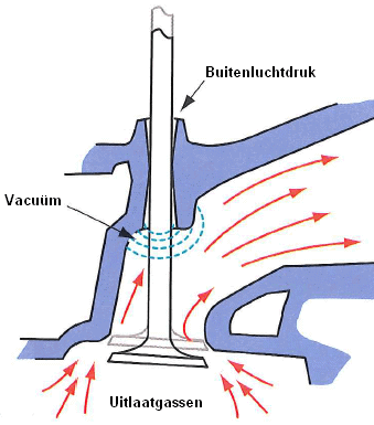
When blue smoke comes from the exhaust, this may be the result of defective valve guides. The valve guides may have become wider (see the image below), which may even cause the valve to have play in the cylinder head. In this situation, oil can enter the intake or exhaust port along the valve. At the top of the valve guide, atmospheric pressure prevails, or sometimes even overpressure due to a higher crankcase pressure. At the bottom of the valve guide, the gases flow toward the exhaust manifold, which creates a vacuum effect. This increases the leakage, because the oil is effectively drawn down along the valve stem. When the oil ends up in the exhaust manifold, it is not burned. The oil is heated and partly evaporates. The result may be that blue smoke comes from the exhaust.
Valve guides can often be replaced separately. For this, the cylinder head must be removed and the valve taken out of the cylinder head. The valve guides can then be replaced. Not all cylinder heads have valve guides that can be replaced separately. Engine reconditioning companies often have a solution for this. Ask a reputable reconditioning company about the options for replacing valve guides.
Different types of valvetrain:
The valves can be operated in different ways. The five different designs are shown in the image below. These different designs and the adjustment methods are discussed later on this page.
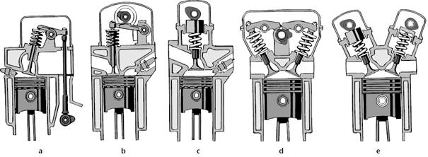
- A: Indirect valve actuation with rocker arms.
- B: Direct valve actuation with roller finger followers.
- C: Direct valve actuation with hydraulic tappets.
- D: Direct valve actuation with rocker arms and multiple valves per cylinder.
- E: Direct valve actuation with hydraulic tappets and multiple valves per cylinder.
For engines without hydraulic tappets (A, B and D), it is necessary to periodically check the valve clearance. More on this in the chapter “Adjusting valve clearance” on this page. For engines with hydraulic tappets, adjusting the valve clearance is not necessary and also not possible; the hydraulic tappets are filled with oil, which eliminates the excess clearance.
Indirect valve actuation:
In the past, engines were built with a camshaft located in the engine block. Nowadays, passenger car engines are only built with an overhead camshaft. The design with the camshaft in the block is disappearing. The disadvantage of this design is that these engines can handle lower maximum engine speeds, because there is a lot of mass between the camshaft and the valve. At high engine speeds, too much play will occur and the valve will no longer open and close at the correct times.
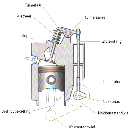
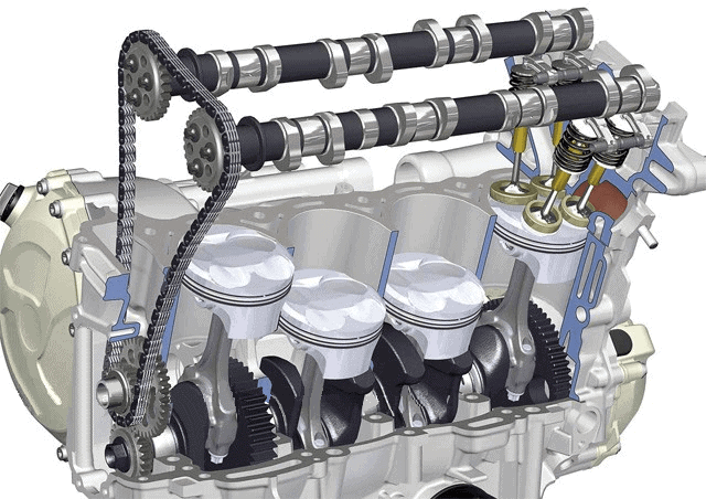
The crankshaft drives the camshaft in the block by means of a short timing chain or belt (see the image below). The camshaft pushes the tappet and pushrod straight upward. The right-hand side of the rocker arm is pushed up. The rocker “rocks” around the rocker shaft, causing the left side to be pushed down. As a result, the valve is pushed downward against the force of the valve spring. When the camshaft has rotated further, the valve spring closes the valve and the rocker returns to its initial position.
Direct valve actuation:
An overhead camshaft is now used exclusively in passenger cars. The camshaft is then placed in the cylinder head. The advantage of engines with an overhead camshaft is that they can handle higher engine speeds than those with a camshaft in the block.
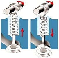
In the left-hand image above you can see that the valve is closed because the valve spring presses the valve shut and that the camshaft rotates clockwise. In the right-hand image, the camshaft has rotated so that the cam pushes the valve downward. The spring is now compressed, causing the valve to move downward. When the camshaft has rotated further, the valve spring will push the valve back up. The valve spring exerts a counterforce of approximately 20 kg.
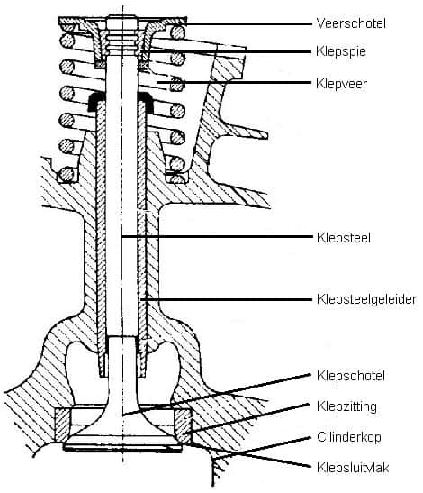
The image shows a schematic representation of a valve with valve spring. Here you can clearly see on which part the valve rests on the valve seat in the cylinder head. At the top are the spring retainer (the part where the cam presses the valve downward) with the valve collet/keeper and the valve spring below it. The collet/keeper secures the valve. To remove the valve from the cylinder head, the collets must be removed. During removal, the spring retainer must be pushed downward against the force of the valve spring (there is special equipment for this). The valve will then be free to move. By removing the two collets with a magnet from between the spring retainer and the valve stem, the valve can be removed from the cylinder head from below.
When refitting, make sure that the correct valve is fitted in the correct location. They must not be swapped. When a new valve is installed, it must be lapped in with special grinding paste. After lapping, the valve will seal properly. The new valve can then be slid through the valve guide and the collets can be put back in place. After that, the valve spring can be released again.
Adjusting valve clearance:
There must always be a certain amount of clearance between the camshaft and the rocker arm or the top of the valve. This clearance allows the material to expand. The clearance must not be too large; the valve will then open less far and for a shorter time. When the clearance is too large, it takes longer before the camshaft pushes the valve open and the valve closes earlier. The clearance must also not be too small; the valve will then open earlier and close later. In that case the valve remains open too long each time. The time the valve is closed is therefore shorter; there is a risk that the valve cannot transfer its heat to the valve seat in the cylinder head and therefore overheats. The valve can then burn.
Nowadays, almost all passenger cars are fitted with hydraulic tappets. However, there are still manufacturers that develop engines where the valve clearance must be adjusted. In cars from the 1990s, the use of hydraulic tappets was not at all self-evident. So there are still plenty of vehicles on the road where the valve clearance must be checked periodically and adjusted if necessary. The factory data often state at which mileage this must be done (often at every major service). There are two different designs for adjusting valve clearance: by means of shims and by adjusting eccentric screws. Both are described below.
When adjusting the valves, you cannot just start at any random point. You must pay close attention to the point when the valves are in “valve rock”. Valve rock means that the camshaft has just closed the exhaust valves and is about to open the intake valves. When cylinder 1 is in valve rock, it means that it is at the beginning of the intake stroke. The piston of cylinder 1 is then at the top. Cylinders 1 and 4 are always at the same height (just as 2 and 3 are at the same height, see the image below). Because the firing order is 1-3-4-2 (think of the work diagram), this means that cylinder 4 is at the beginning of the power stroke. After cylinder 4, cylinder 2 is next and then cylinder 3.
In the image below, the piston of cylinder 1 is at TDC. The cams are pointing downward; the intake valves have just closed and the exhaust valves are about to open. At that moment, the valves of cylinder 4 can be adjusted; the cams there are pointing upward.
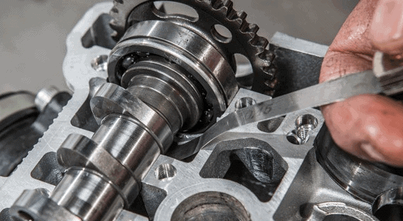
The valve clearance is measured with a so-called “feeler gauge“. The feeler gauge has several metal strips of different thicknesses, each 0.05 mm thicker than the other. By sliding one of the strips between the camshaft and the valve, you can check how much clearance is present. The relevant strip must not slide through too easily; in that case, the valve clearance is greater than the value of the strip. When the strip does not fit between them or moves only with great difficulty and jams, the strip is too thick. Some resistance must be felt when the strip is moved between them.
Adjusting valve clearance using shims:
In this case, the thickness of the shim determines the valve clearance. In the image below, the shim is indicated in red. By replacing the shim with a thicker one, the valve clearance will become smaller. There is then less space between the camshaft and the shim. Below the image it is explained how the valve clearance must be adjusted. To adjust the valves, the cam of the relevant valve must be pointing upward, as shown in the image below. If the cam is rotated, the measurements will be incorrect. When adjusting the valves of a four-cylinder engine, the following procedure must be followed:
- Cylinder 1 in valve rock = Adjust valves of cylinder 4.
- Cylinder 2 in valve rock = Adjust valves of cylinder 3.
- Cylinder 3 in valve rock = Adjust valves of cylinder 2.
- Cylinder 4 in valve rock = Adjust valves of cylinder 1.
The factory value for the above valve clearance may, for example, be 0.35 mm. There must therefore be a gap of 0.35 mm between the shim and the camshaft when the cam is pointing upward. The gap between the two parts can be measured with the feeler gauge. If the 0.35 mm strip passes through very easily without any noticeable resistance, this means that the distance between the valve and the camshaft is greater than 0.35 mm. The valve clearance is then too large. When a 0.45 mm strip from the feeler gauge hardly fits between them because a lot of force is needed to push it in, the strip is too thick. The actual clearance then lies between 0.35 and 0.45 mm. To be sure, a 0.40 mm strip can be inserted. If it drags slightly but can still be moved back and forth (there should be noticeable resistance), then you know for sure: the valve clearance is 0.40 mm instead of the specified 0.35 mm.
Because the valve clearance is too large, a thicker shim must be installed. The thickness is often printed on the shims. In that case, read the value of the shim that is too thin. For example, that is 2.75 mm.
The valve clearance is too large; the shim must be 0.05 mm thicker than the one that is installed, namely the 2.75 mm one. When a shim of (2.75 + 0.05) = 2.80 mm is installed, the valve clearance will be correct. In that case, install the 2.80 mm shim, rotate the crankshaft two revolutions so that the correct valves are in valve rock again, and check the valve clearance once more.
Special removal tools are often available to replace the shims easily. An example of this can be seen in the image.
Adjusting valve clearance using adjustable eccentrics:
A frequently used system is the adjustable eccentric. The adjusting screw can only be turned once the locknut has been loosened by a quarter turn. When the adjusting screw is then turned, the gap between the valve stem and the rocker arm will immediately become larger or smaller. By then tightening the locknut, the adjusting screw is locked again.
Here too, of course, the valves of the correct cylinder must first be in valve rock! By using a feeler gauge of the correct thickness (i.e. the same value as the factory specification) between the valve stem and the rocker arm, it can be determined whether the valve clearance is too large, too small or correct. By turning the adjusting screw and constantly moving the feeler gauge between them, the correct position of the adjusting screw can be found where the valve clearance is correct. Then tighten the locknut and check whether the clearance is still the same. There is a good chance that the adjusting screw will rotate slightly when the locknut is tightened, unless special tools prescribed by the manufacturer are used.
Multi-valve technology:
Every four-stroke engine has at least 1 intake valve and 1 exhaust valve. More powerful and more efficient engines often have 2 intake valves and 2 exhaust valves. Some types have 2 intake valves and 1 exhaust valve, or 3 intake valves and 1 exhaust valve.
There are two major advantages to using multiple valves, namely:
- The valves will have a somewhat smaller diameter, which leads to a lower mass (less weight) per valve. The biggest advantage of this is that the valves will not start floating at high engine speeds. Floating valves mean that when the engine is running at a high rpm (e.g. 5000 rpm) the valves open and close so quickly that the valve springs no longer have time to push the valve closed. The valve therefore does not fully seat on the valve seat. As a result, the piston may hit the valve, or the valve may overheat because it can no longer dissipate its heat into the valve seat. Because of the multiple valves, the valves are lighter and the valve springs have enough time to close the valve.
- Due to the lower mass per valve, the valves can be closed more quickly. This makes it possible to apply variable valve timing, in which the position of the camshaft is adjusted at a certain engine speed or load.
Variable valve timing and valve lift height:
Modern engines often use variable valve timing. Some engine manufacturers also apply variable valve lift height (including BMW). These chapters are described separately on the pages: