Introduction:
The MOSFET (this is the abbreviation of Metal Oxide Semiconductor Field Effect Transistor) is used in many microcontrollers. The MOSFET is best compared to a regular transistor, because both the FET and the transistor have three terminals and are thus able to control currents. The difference between the FET and the regular transistor is that the FET only needs a voltage to switch, whereas the transistor needs current. The FET is therefore controlled without energy consumption, which benefits the minimal heat development in a microcontroller.
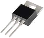
The image shows a MOSFET. The three pins are the terminals “gate”, “drain” and “source”.
MOS transistor as a switch:
With the N-MOS transistor, the gate must be positive in order to switch the FET on. The P-MOS transistor is not yet described on this page.
The left terminal is called the gate (g), the upper one is the drain (d) and the lower one is called the source (s).
When a positive voltage is applied to the gate, a high concentration of electrons is formed directly under the gate insulation under the influence of the electric field. This creates an n-channel between the drain and source, which makes direct conduction between the drain and the source possible. The arrow in the symbol indicates the direction of electron flow. With the n-MOS the arrow points towards the channel.
The gate is also called the control electrode. Compared to the regular transistor, the drain corresponds most closely to the collector and the source to the emitter. Normally, no conduction is possible between the drain and the source, because there is an np-pn junction between them. This is comparable to two diodes with their cathodes connected together.
The diagram shows a battery, switch, LED and MOSFET. When the switch is closed, a voltage is present on the gate. This creates conduction between the drain and source, causing a current to flow. Because a current flows through the resistor and the LED, the LED will light up.
In this example, the gate is controlled by the manually operated switch. In reality, the gate is controlled by an ECU. The drain is connected to the negative terminal of an actuator; in the diagram, the LED is the actuator. The source is connected to the ground of the battery.
MOS transistor characteristic:
Just like the regular transistor, the MOSFET also has a characteristic. With this characteristic it can be determined what the voltage on the gate must be to control the actuator with the MOSFET.
In the image below, a diagram on the left shows a 5 Watt bulb that is controlled by the MOSFET. On the right, the characteristic of the MOSFET is shown. On the vertical axis (the Y-axis) of the characteristic, the current through the drain is shown. On the horizontal axis (the X-axis), the voltage difference between the drain and the source can be read.
If the transistor is in conduction because the ECU supplies the gate with a supply voltage, a current will flow and the bulb will light up. The voltage measured by the voltmeter in this situation is 12 volts. With the 5 Watt bulb, a current of 0.42 Ampere (420 mA) flows through the drain.
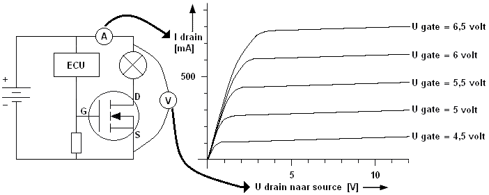
Now that the voltage of 12 volts and the current of 420 mA are known, these two intersection points can be plotted in the characteristic. A line can be drawn between these two points. This is the load line. Using this load line, it can be determined what the minimum voltage on the gate must be to allow the MOSFET to conduct. To be sure that the MOSFET is driven fully into conduction, the voltage on the gate is always taken higher than necessary. Think here of the factor 1.5 Ibk with the regular transistor.
In the characteristic it can be read that the ideal voltage on the gate is 5.5 volts. The higher the current through the drain, the higher the voltage on the gate must be to allow the MOSFET to conduct.
Related page: