Spring-loaded check valve:
A pressure relief valve protects the hydraulic circuit against excessively high pressures. A pressure relief valve is also called a pressure limiting valve or safety valve. Without this valve, the pressure in the system could become too high, causing seals to leak or components to fail.
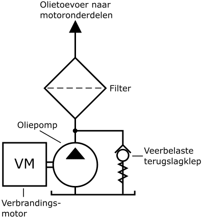
The simplest design is the spring-loaded check valve, which is shown in the following image. As an example, we use the oil pump with filter and safety system of an internal combustion engine. The oil pump is driven by the crankshaft. As soon as the oil pressure overcomes the spring force on the ball of the check valve, an opening is created and the oil flows back to the reservoir. We find this type of pressure protection in lubrication systems where the maximum oil pressure must not exceed approx. 5 bar.
In addition to the spring-loaded check valve, in hydraulics we also often encounter direct and indirect pressure relief valves.
Direct-acting, spring-loaded pressure relief valve:
The direct-acting relief valve is very similar to the spring-loaded relief valve shown above. However, the differences and advantages of the direct-acting pressure relief valve are:
- a relatively simple and inexpensive design;
- fast response to pressure surges and fluctuations in the system;
- seat valves seal leak-free.
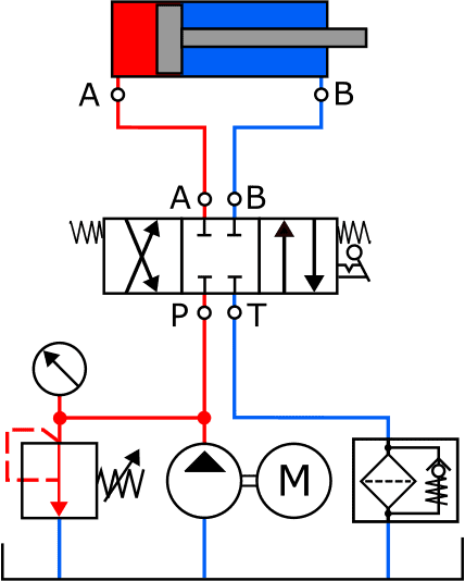
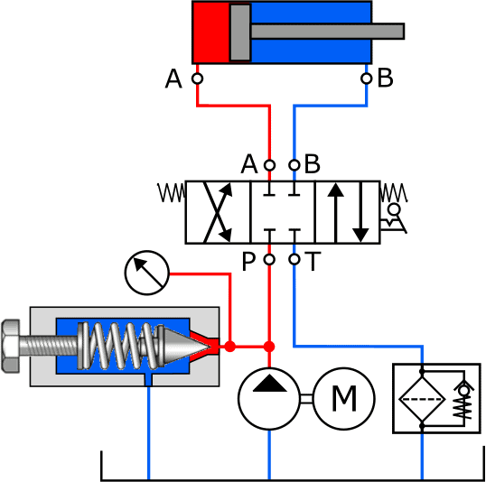
The two images below show the diagrams with a spring-loaded relief valve with the symbol (left) and a drawing of the component (right).
The pressure relief valve is normally closed by a spring; no fluid can pass through. In the diagram we see the spring with an arrow in it: this means that the spring is manually adjustable. In the image on the right we see the screw used to tension the spring. The further the screw is turned in, the higher the opening pressure becomes.
At the moment the fluid pressure reaches the set pressure, it pushes the conical plunger inward against the spring force. An opening is created through which the fluid can flow directly to the return. The pressure on the pump side (the red line) does not increase any further.
The disadvantage of the direct-acting pressure relief valve is that there is always some internal leakage.
Calculating required spring force for pressure relief valve:
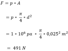
The following calculation shows how much spring force is needed to keep the valve closed at a certain pressure. We use the following data:
- pressure to be set (p) = 10 bar (is equal to 1,000,000 Pa);
- valve orifice = 25 mm.
The force that the spring must provide is quite high. At higher pressures, a heavy spring design is required.
An alternative is an indirect pressure relief valve or a pilot-operated pressure relief valve.
Indirect pressure relief valve:
In the previous paragraph it can be seen that the spring force in a direct pressure relief valve must be no less than 491 N to keep the valve closed at a pressure of 10 bar.
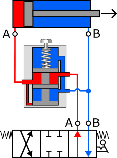
That makes the direct pressure relief valve unsuitable for hydraulic systems that operate with higher pressures (>100 bar) and a large flow rate. To avoid heavy spring constructions, systems with high working pressures use an indirect pressure relief valve. In the indirect pressure relief valve there is fluid pressure on both sides of the main valve, so the spring can be made smaller. The three images below show the schematic principle of this type of pressure control valve. The indirect pressure relief valve contains two valves, each of which is held closed in its rest position by its own spring:
- pilot valve;
- main valve.
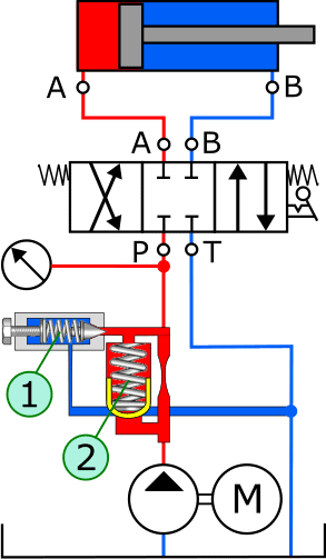
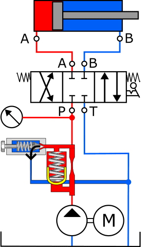
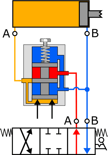
The system pressure from the hydraulic pump is connected directly to the bottom of the pressure control valve and reaches the pilot valve (1) via a restriction in the supply line and the main valve (2). As long as the system pressure does not exceed the pressure set with the pilot valve, both valves remain closed (image A). When the pressure rises too high, for example when the cylinder has reached its end position, the fluid pressure pushes the pilot valve (1) inward against the spring force (image B). The oil now flows via the restriction and the opened pilot valve, through the return channel to the reservoir.
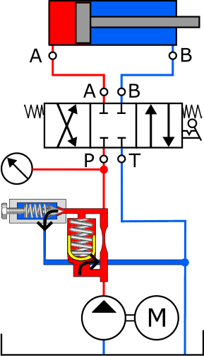
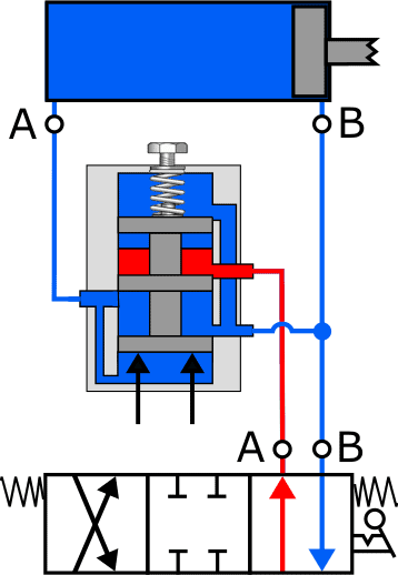
The restriction causes a pressure difference across the main valve even at a low flow rate. This pressure difference causes the main valve to open against the spring force (image C). In this way the full pump output can be discharged to the reservoir via the main valve.
Pressure reducing valve:
The task of the pressure reducing valve is to reduce the pressure in the hydraulic system, or only in a part of the system, to a desired value and to keep it constant.
The following diagram shows the symbol of the pressure reducing valve in the pressure line between the control spool and the cylinder. The symbol looks somewhat similar to that of the pressure relief valve.
The pressure reducing valve allows the fluid pressure to pass through as long as the pressure has not reached the set value. This allows the cylinder to be controlled without any problems.
Once the set pressure has been reached, the pressure reducing valve closes the supply and initially keeps the pressure constant. If the pressure on the cylinder side continues to rise, the valve reduces this pressure by directing it to the return.
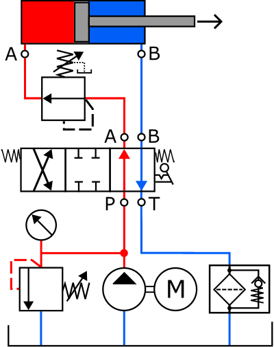
The three diagrams below show the operating principle of the pressure reducing valve in three situations. For convenience, only part of the diagram is shown: the hydraulic pump, pressure relief valve, etc. are omitted due to their size. The piston rod in figs. B and C has also been shortened due to the image size.
- A. The pressure reducing valve is in the rest position. The fluid from the hydraulic pump flows unimpeded to port A of the cylinder;
- B. The piston in the cylinder has reached the end position. The pressure in the supply line increases. The control plunger in the pressure reducing valve closes the supply from the control spool to the cylinder. The pressure in the cylinder is kept constant (yellow);
- C. When the load at the end of the piston rod increases, this will affect the fluid pressure in the cylinder. The control plunger moves even further upward due to the pressure increase at the bottom. This opens the return channel and allows the fluid to flow from the cylinder to the reservoir.
After the fluid pressure has dropped, the process takes place in reverse: when the pressure decreases, the plunger closes the return channel and keeps the pressure constant, after which the plunger moves further downward and the pressure increases again. The pressure at which the pressure reducing valve must operate can be adjusted manually by turning the screw further in or out.
Sequence valve:
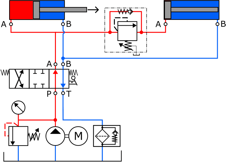
With a sequence valve, for example, two cylinders can be actuated in an order desired by the designer. The sequence in which they extend cannot be controlled during operation; the least loaded cylinder will move first.
In the illustration below, the left cylinder will be extended first. As soon as it has reached its end stop, the pressure in the red supply line increases. The sequence valve opens at a certain pre-set pressure. Once the spring force in the sequence valve has been overcome, the fluid flows to the right cylinder, which will then start to move. A sequence valve is in fact a pressure relief valve with a built-in check valve. The check valve opens at the moment the control spool switches the supply to port B of the cylinder and the return to A.
Related page: