Topics:
- BMW engine
- Initial project work
- Checking the oil pump
- Removing the distributor
- Starting and charging system
- Frame with monitors and computer
- Dashboard with electrical installation
- Cooling
- Fuel tank
- Intake tube, air filter, crankcase ventilation hoses
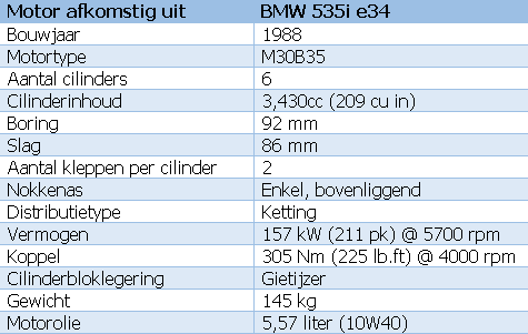
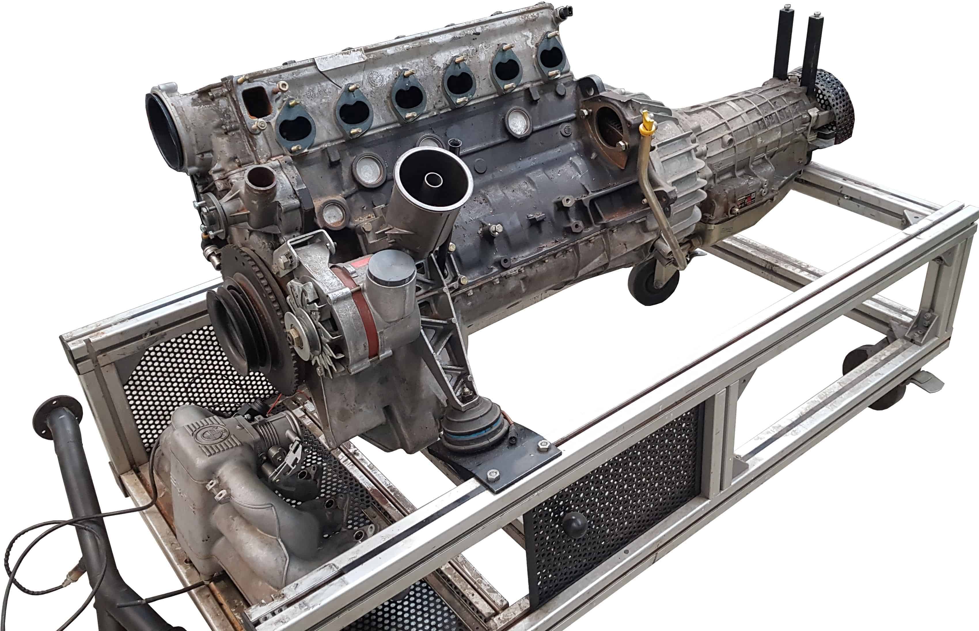
BMW engine
The decision to use this BMW engine for this conversion project was made quickly; there were too many defects for students to work on it, but it was still good enough to refurbish. The engine comes from a BMW 5 Series E34. The table below shows the engine specifications.
The initial work of the project:
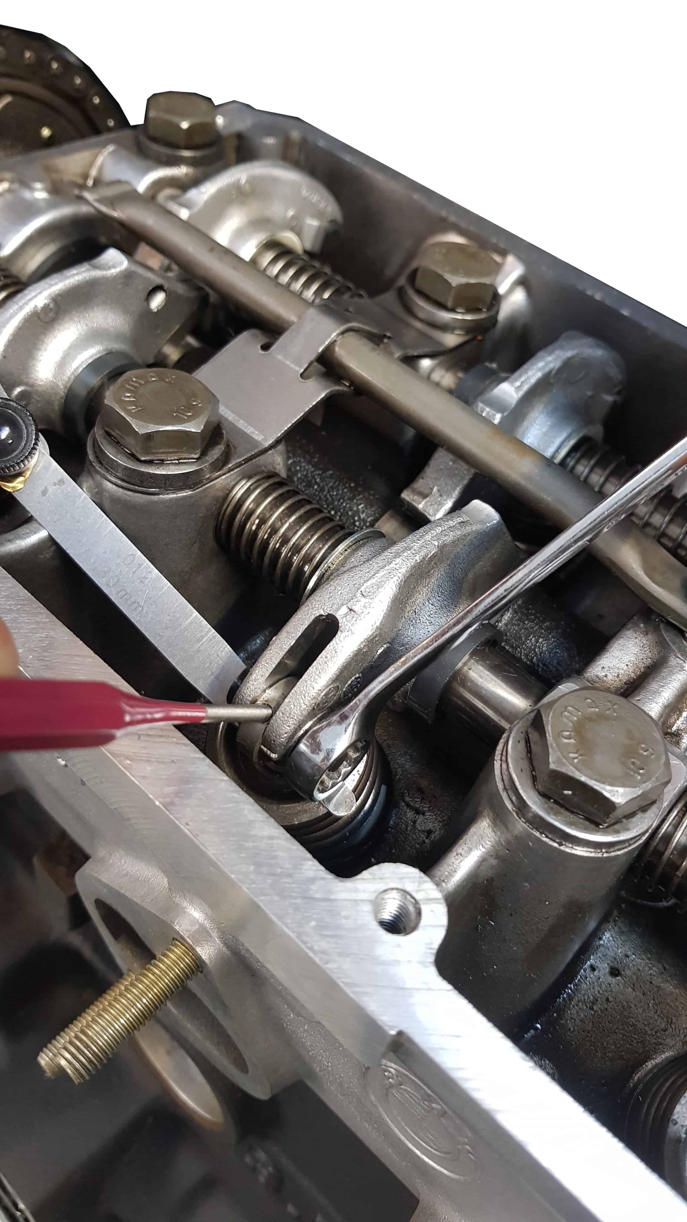
As mentioned earlier, the BMW engine is in good condition. A highly motivated student immediately started removing ancillary components. The wiring harness, original ECU and the ODB1 diagnostic connector are removed permanently. Other parts such as the valve cover, the manifolds including exhaust, and the frame with radiator are inspected, cleaned, and later reinstalled with new gaskets, O-rings and hose clamps. The valves are adjusted, and the coolant pump is preventively replaced due to its age and rust.
Of course, the oil is changed and the cooling system cleaned. At a later stage, after the engine has been running for at least an hour, the fluids will be changed again and the filters replaced.
The photos below show the start of the project with the ancillary components being dismantled and the adjustment of the valve clearance. Click on the photos to open them in full size.
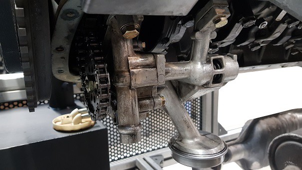
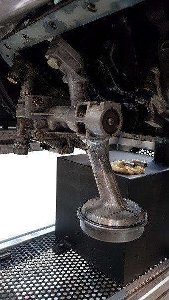
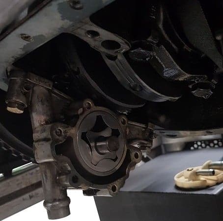
Checking the oil pump:
While operating the starter motor, attention was paid to the oil circulation in the cylinder head. During cranking, no oil supply to the camshaft, etc. could be seen. It was not known whether the oil pump and pick-up strainer were in good condition; after all, the engine has been used in the past for practical assignments. Something might have been missing in the oil supply. Therefore, it was decided to remove the oil pan and check the oil pump and strainer.
After disassembly and inspection, we concluded that the oil pump and its components were in order. The parts were reassembled and the oil was refilled.
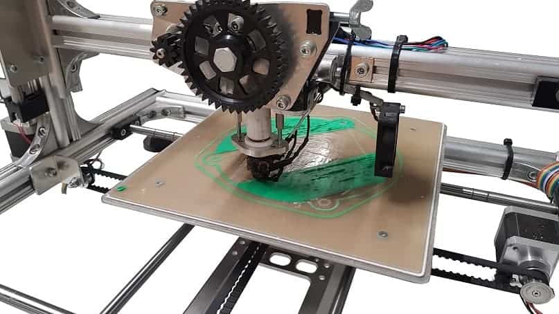
Removing the distributor:
The ignition system will be implemented using a DIS coil. We remove the original coil and distributor. Removing the distributor left an uncovered hole in the cylinder head. In it you can see the end of the camshaft and the camshaft seal. At a later stage, in combination with a MegaSquirt III (for now we are using the MS-II), a camshaft position sensor can be fitted here. To cover everything neatly, a cover plate was drawn in AutoCAD and created with a 3D printer. The photo was taken 10 minutes after the print started. In total, the printing took 3.5 hours.
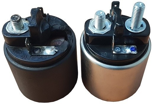
Starting and charging system:
One of the visible defects was a faulty starter relay. At least, the threaded stud had broken off. Repairing the starter relay seemed impossible. Fortunately, the cost turned out to be manageable: for €25, the local overhaul specialist supplied a new starter relay. The image shows the defective one (left) and the new one (right).
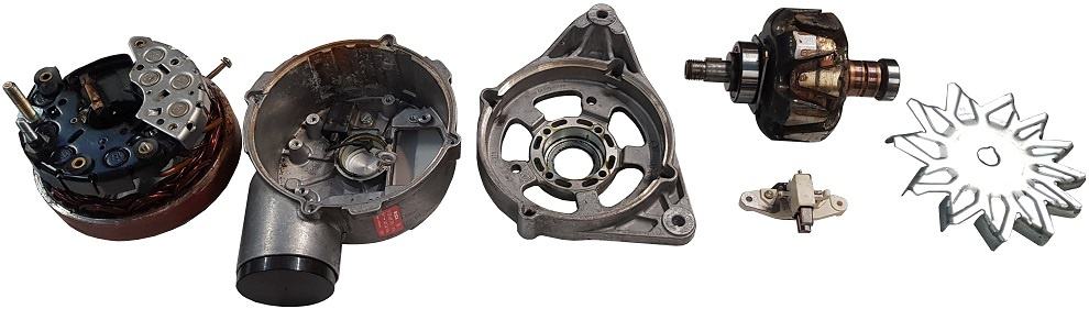
We were less fortunate with the alternator. After the positive cables were connected, a short circuit somewhere in the system was discovered while connecting the ground cable. After a short search, the cause was found: the B+ of the alternator was making contact with the housing. The resistance between B+ and the case was 0.2 ohms. The alternator was immediately removed and opened. What turned out to be the case? The D+ connection was contacting the housing because the internals were not sitting straight in the housing and the plastic bushing was broken. The alternator could never have functioned in this condition; presumably, a student took the alternator apart in recent years, after the engine had stopped running, and did not reassemble it correctly.
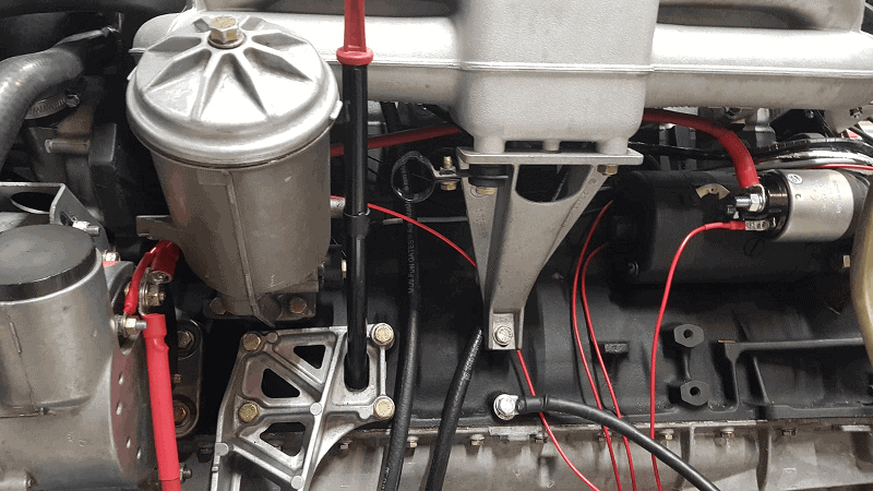
After repairing the starter motor and alternator, work began on installing the wiring. The red wires can be seen in the image below.
The positive cable from the battery is connected to the B+ terminal of the alternator. The positive cable to the starter motor is also mounted on this same stud.
The D+ wire on the alternator is connected via the charge warning lamp on the dashboard to a fuse (terminal 15). The control wire for the starter motor (terminal 50) is operated by the start button on the dashboard.
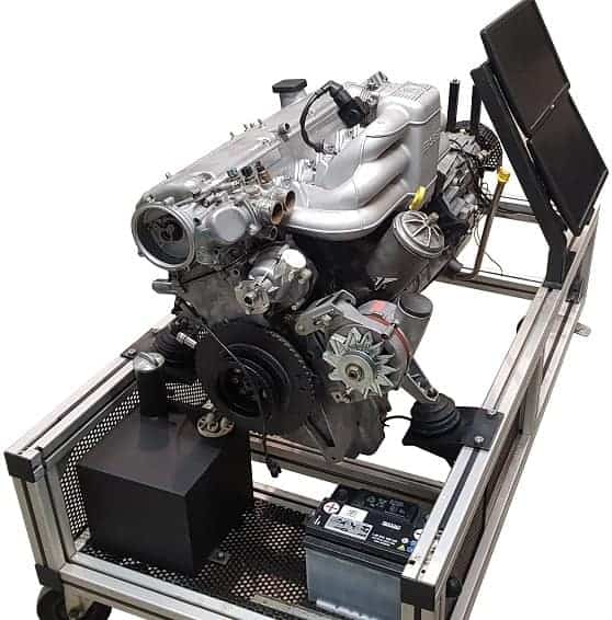
Frame with monitors and computer:
A desktop computer with two monitors will be mounted on the engine frame. These monitors will eventually display the gauges of the dashboard and the maps. It will also be possible to demonstrate oscilloscope (Picoscope) measurements on a screen.
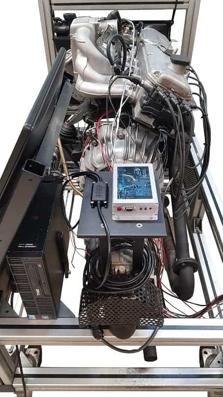
The frame has been modified so that the two monitors can be mounted one above the other. The screens are tilted at a certain angle so that they are clearly readable when standing in front of the engine.
The desktop computer is placed behind the monitors on the engine frame. The PC is a Dell Optiplex XE (Core2Duo 2.6 GHz, 4 GB RAM). This type of computer is designed to run 24/7 in heavy-duty industrial applications, for example in hot, dusty environments. This makes the PC highly suitable for use on the engine frame while the engine is running. The standard hard drive has been replaced with an SSD to minimise the risk from vibrations. The PC and monitors are sponsored by Zenid.net.
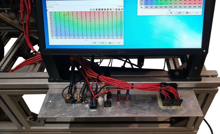
Dashboard with electrical installation:
Under the monitors a panel with several components has been installed. The image shows the back of the panel with the wiring.
From left to right:
- Master disconnect switch (ground)
- Ignition switch (terminal 15) and start button (terminal 50)
- Cooling fan switch
- Terminal 15 indicator lamp
- Charge warning lamp D+
- Fuse box 1 (6x)
- Fuse box 2 (6x)
The wiring diagram has recently been modified. The new version will be added to this page soon.
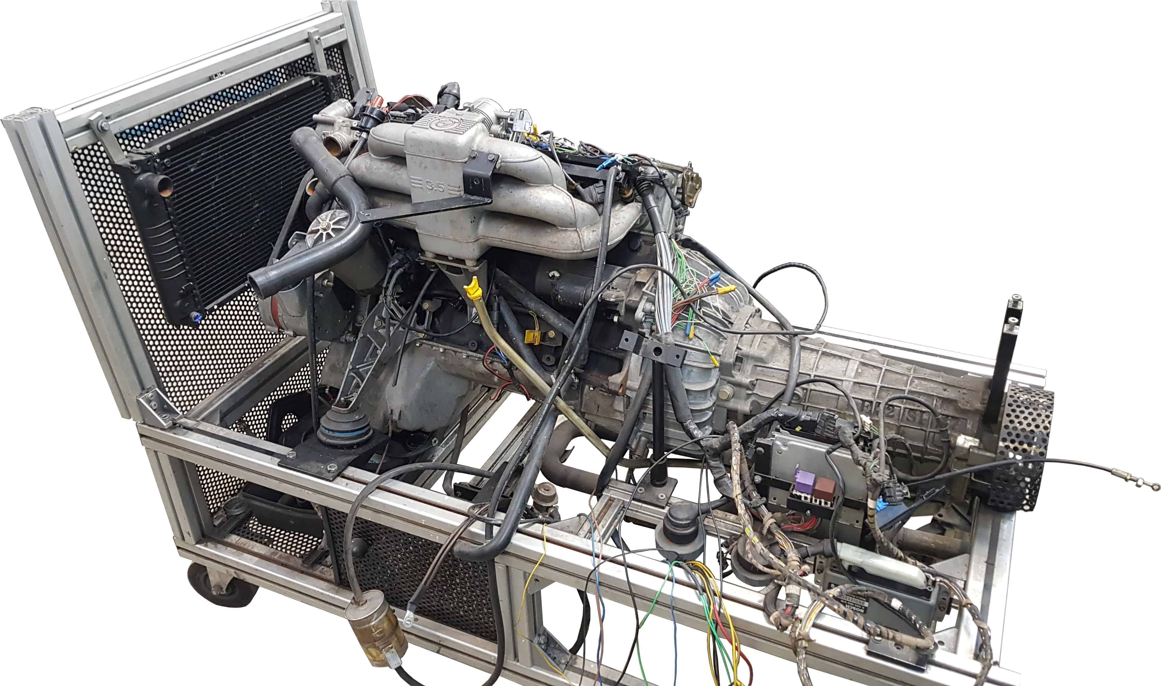
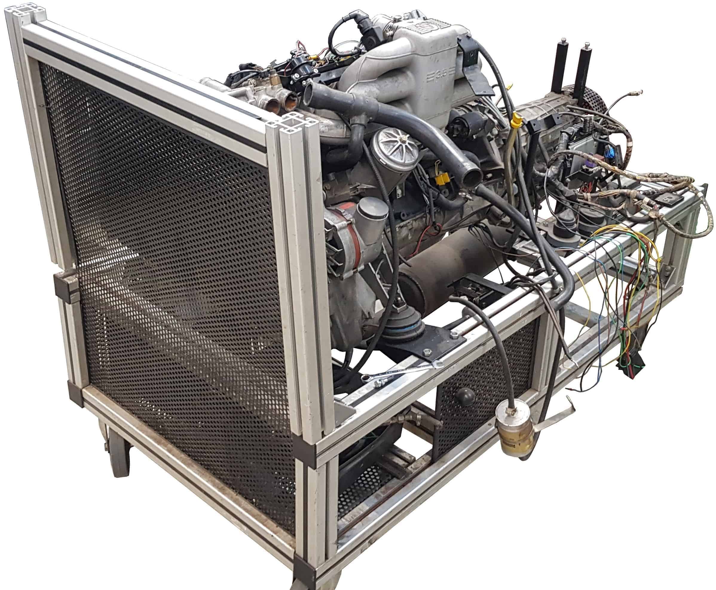
Cooling:
The original parts of the cooling system were incomplete, dirty and/or defective. In addition to a new coolant pump that has been replaced as a precaution, the following parts have also been newly installed:
- Radiator;
- Coolant reservoir;
- Six new radiator hoses;
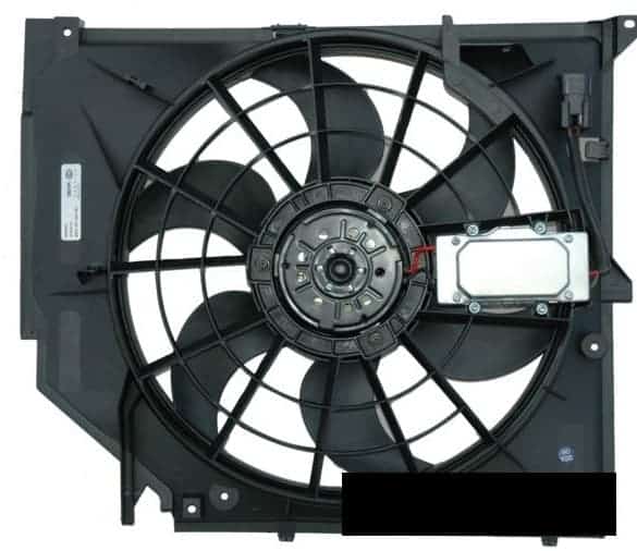
- Cooling fan.
These components are not from an E34, but from an E46 (3 Series). The size of the radiator, the diameter of the hoses and the power of the cooling fan are sufficient to provide adequate cooling. The cooling fan has a power of no less than 390 W.
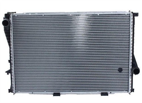

The images above show the radiator and the expansion reservoir. These components belong together; the reservoir can be attached to the top and bottom of the radiator. A special frame is needed in between for this. This frame is not shown.
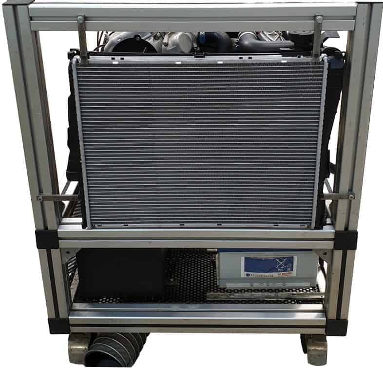
The image below shows the cooling fan. The fan also belongs to the radiator and the reservoir; these three components are attached together. The image below also shows the moment when the cooling components, consisting of the just-described parts, were hung in the frame. In this way, the height and the distance between the thermostat housing and the pipe of the reservoir could be adjusted. In the end, an S-shaped coolant hose will be fitted between them.
The radiator is mounted as follows:
- rubber blocks have been placed between the radiator and the horizontal bar of the engine frame, so the radiator can rest on them;
- thanks to the metal rods on the left and right, the radiator is clamped in all directions;
- the metal rods at the top ensure that the radiator cannot tilt.
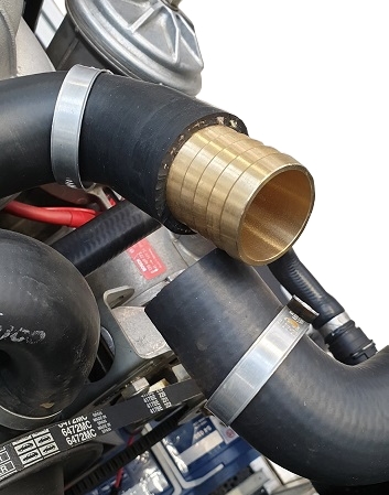
A standard coolant hose with the original dimensions is attached to the flange that clips onto the top of the radiator. The bends in the hose do not match the space we have available on this engine. That is why the standard coolant hose was removed from the flange and the crimped ring around it was ground off. Instead, two hoses with a diameter of 38 mm (G4278-17033) were cut to size and mounted in an S-bend.
Some time was spent looking for a good way to connect the two hoses. Plastic PVC pipe turned out to be too soft and deformed when the coolant was hot, so it was unsuitable. The car parts shop started searching and finally came up with a brass hose connector (WK 34305) that fit perfectly. Thanks to the ribbed exterior, the hoses clamp perfectly.
The image below shows the brass hose connector that is halfway inserted into one coolant hose. The other coolant hose is also mounted on the hose connector and the hose clamps have been tightened firmly.
The same type of hose connector is also mounted between two other coolant hoses at the bottom of the radiator.

Fuel tank:
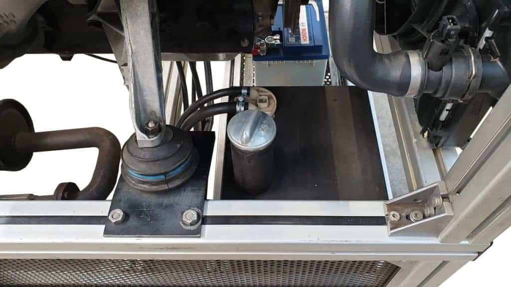
The 20-liter fuel tank was already in the same position in the old setup. The tank is attached to the engine frame and is located in the corner, next to the battery, under the lower radiator hose. An original chrome cap seals the tank.
The image below shows the fuel tank and the two fuel hoses. One of these is the supply and the other the return. The hoses run to the fuel rail, in which the injectors are mounted. These components are described in the chapter “actuators”.
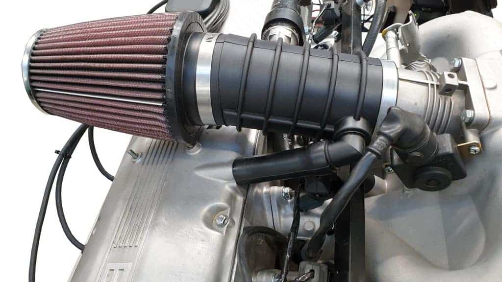
Intake pipe, air filter, crankcase ventilation hoses:
The original intake pipe, crankcase ventilation hoses, PWM idle control valve and the air filter housing were missing. Even if some parts had been present, there was a good chance that, due to age and frequent disassembly/assembly, they would have had small cracks. These parts, with the exception of the PWM control valve, were purchased new. The intake pipe and crankcase ventilation hoses were ordered from a BMW dealer. The original air filter housing would not fit neatly onto the engine frame, so the decision to install an open air filter was made quickly. The air filter (K&N, KNRC-3250) had the same diameter as the intake pipe.
Using AutoCAD and a 3D printer, an adapter was designed and printed that could be mounted between the air filter and the intake pipe.