Topics:
- Crankshaft position sensor (CPS)
- Lambda sensor
- Coolant temperature sensor (CLT)
- Intake air temperature sensor
- Throttle position sensor (TPS)
Crankshaft position sensor (CPS):
On the BMW engine, the crankshaft position sensor is mounted at the front of the engine above the ring gear of the crankshaft pulley. From the signal of this sensor, the ECU can determine the following:
- the crankshaft speed: determined by the speed at which the teeth move past the sensor.
- the crankshaft position, which is determined on the basis of the reference point of the ring gear. One or more machined-off teeth serve as the reference point.
The crankshaft pulley is of the “60-2” type. The disc contains 60 teeth, two of which are machined off. The machined-off teeth serve as the reference point. The actual TDC of the piston of cylinder 1 occurs 16 teeth later.
The number of degrees between the reference point and the actual TDC can be determined with a simple calculation:
Every time a tooth moves past the sensor, the crankshaft has rotated (360 / 60) = 6 degrees.
If the reference point and the actual TDC are 16 teeth apart, that is (6 * 16) = 96 degrees.
This information is very important for the engine management system. After the reference point has been registered, the ECU can determine, by counting the teeth, at which moment injection or ignition must take place. In the situation where the ignition needs to be advanced by 30 degrees, the ECU must ensure that 5 teeth before the actual TDC (5 teeth * 6 degrees = 30), so 13 teeth after the reference point, the spark plug fires. At this point no allowance has yet been made for the charge time of the primary coil in the ignition coil, which also takes time, so in practice the ECU starts charging the primary coil a few crankshaft degrees earlier. We will return to this in the paragraph about the ignition coil in the chapter on actuators.
Lambda sensor:
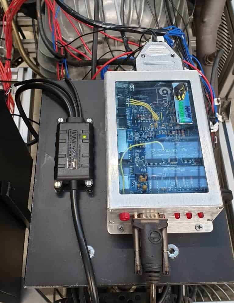
The standard lambda sensor has been replaced by a Bosch LSU 4.2 5-wire wideband sensor. The sensor is connected to the Innovate LC-2 digital lambda controller. This controller converts the signal from the lambda sensor into a digital signal and sends it to the MegaSquirt ECU.
Specifications Innovate LC-2 O2-controller:
Power | |
| Operating Voltage | 9.8V to 16V DC |
| Input Current, O² heater initial warm-up | 2.0A nominal, 3A max |
| Input Current, O² normal operation | 0.8A nominal, 1.1A max |
Environmental | |
| Operating ambient temperature | 0° to 140° F (−17.78° to 60° C) |
| Storage ambient temperature | −40° to 185° F (−40° to 85° C) |
| Water resistance | Splash resistant, non-submersible |
Sensors | |
| Compatible Types | Bosch™ LSU4.2 & Bosch™ LSU4.9 |
| Bosch™ Heater Control | Digital PID via pump-cell impedance |
Measurements | |
| Lambda | .5 to 8.0 |
| Air/Fuel Ratio | 7.35 to 117 (gasoline), Fuel Type Programmable |
Accuracy | |
| For Lambda | Accurate to +/- .007 (.1 AFR) |
Response Time | |
| Free Air to Lambda | < 100 mS ( < 25 mS typical) |
Inputs | |
| Serial | 1, Innovate MTS Compatible |
Outputs | |
| Analog | 2, 0-5VDC, 10 bit resolution, programmable |
| Serial | 1, Innovate MTS Compatible |
Communication | |
| Serial | MTS (Innovate Modular Tuning System) compatible |
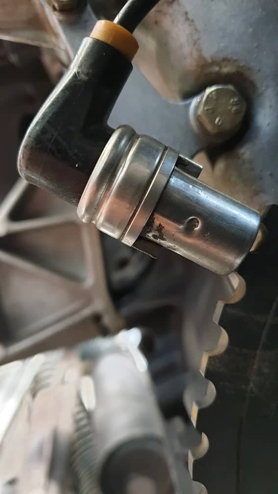
Coolant temperature sensor (CLT):
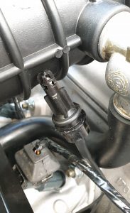
Originally, the engine is equipped with two sensors that both measure the coolant temperature. The image below shows the thermostat housing with two coolant temperature sensors and a thermo switch for the cooling fan. We do not use the left-hand sensor. The middle one is connected to the MegaSquirt ECU. The reason that we use only one sensor is explained below. We also do not use the thermo switch; at the moment, we switch the cooling fan on or off with a manually operated switch. Later, the control will also be handled by the MegaSquirt.
Why two coolant temperature sensors? And why do we only use one?
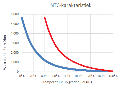
An NTC sensor has a logarithmic characteristic. The resistance decreases as the temperature increases. The blue characteristic in the image shows the greatest resistance change between 0 and 40 degrees Celsius. With increasing temperature, the resistance drops less quickly.
The red characteristic also drops with increasing temperature, but here the greatest change can be seen between 40 and 80 degrees.
We are mainly interested in the temperature up to 60 degrees Celsius in connection with the settings for cold start. Think of fuel enrichment and air bypass via the idle control valve. Above 60 degrees Celsius no further enrichment is required.
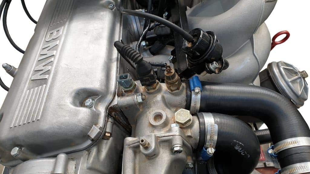
Intake air temperature sensor:
The original sensor is built into the air flow meter. However, this air flow meter has been removed. That means that a temperature sensor must be installed elsewhere.
We use a universal NTC sensor. The brand and origin are unknown. The important thing is that we measure the resistance values with a temperature change, and then enter them into the TunerStudio program.
The temperature sensor is mounted in the intake duct near the idle control valve. The sensor is clipped into the hose. The sensing element is located in the intake duct and measures the temperature of the passing air.
Because there was no connector on the sensor, the wires were soldered to the terminals and protected with heat shrink tubing.
Throttle position sensor (TPS):
Information to follow…