Topics:
- Determining and installing sensors for the engine management system
- Crankshaft position sensor
- Trigger wheel
- MAP sensor
- Coolant temperature sensor
- Lambda sensor
Determining and installing sensors for the engine management system:
The engine management system requires a number of sensors. Sensors serve as the “input” of the system. Sensors convert a physical quantity into an electrical signal – one that can be processed by a computer – in this case by the MegaSquirt.
When assembling the MegaSquirt, the components that are to be mounted on the engine must be taken into account, because the build of the MegaSquirt can differ depending on these choices.
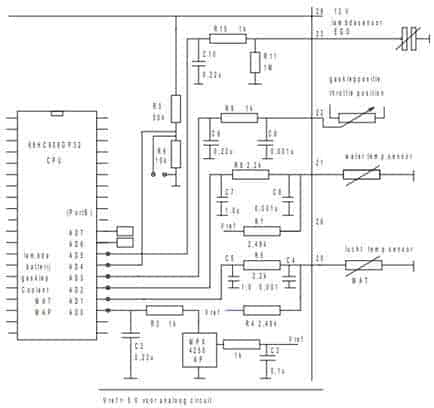
The illustration shows the various sensor circuits in which these components are located. The input signals shown in the figure are from the lambda sensor, the throttle position sensor, the coolant temperature sensor and the air temperature sensor.
Besides the sensors, the diagram also contains a number of resistors and capacitors. The combination of these components forms filters; these filters serve to capture interference and noise. When the sensor signal is distorted by noise, this can have major consequences for the control of the actuators, and therefore also for the operation of the engine.
Crankshaft position sensor:
An important input for the engine management system is the crankshaft speed.
The crankshaft speed is measured using a crankshaft position sensor and a trigger wheel. The crankshaft position sensor has two important functions:
- Based on the frequency of the signal, the crankshaft speed can be determined;
- The missing tooth in the trigger wheel indicates the crankshaft position at which the pistons of cylinders 1 and 4 are a number of degrees before TDC.
The engine speed influences the control of the injectors and the ignition. The missing tooth in the 36-1 trigger wheel is important for determining the ignition and injection timing. A Hall sensor was chosen as the rpm sensor, rather than an inductive pickup. An inductive sensor generates an AC voltage that must be converted into a DC voltage in the MegaSquirt controller. A Hall sensor generates a square-wave signal, which is amplified by an internal or external pull-up resistor to a voltage of 5 or 12 volts. This makes the Hall sensor more suitable for providing a reliable signal. For assembling the MegaSquirt, this choice must be made in advance; both sensors require a different circuit layout.
Trigger wheel:
The crankshaft position sensor measures a change in the air gap of a trigger wheel mounted on the engine. On the Land Rover engine there is originally no crankshaft position sensor and therefore no trigger wheel either. The trigger wheel therefore had to be retrofitted. A lot of thought went into the location and position of the trigger wheel. Options were:
- A disc with 36 teeth mounted on the outside of the crankshaft pulley using a clamping or bolted connection.
- Modifying the existing crankshaft pulley by milling teeth out of the pulley.
It is common practice to use a 36-1 or a 60-2 trigger wheel. The 60-tooth wheel is mainly used for larger diameters. The 36-1 is suitable for use because of the tooth width. It is very important that the trigger wheel has as little runout as possible. Runout means a change in the magnetic field between the sensor and the teeth of the trigger wheel. This can have adverse effects on engine operation and should of course be prevented. For this reason, modifying the existing crankshaft pulley was preferred. The outer rim of the existing crankshaft pulley was machined on a milling machine. By removing material, notches were created. The remaining 36 teeth allow the sensor to measure the changes in the magnetic fields. One tooth was ground off to create the reference point. The picture below shows the modified crankshaft pulley.
At the top side of the trigger wheel, directly under the sensor, the ground-away tooth is visible. When the crankshaft is in this position it does not mean that the pistons of cylinders 1 and 4 are at TDC, but that these pistons are 90 degrees before TDC, which corresponds to 9 teeth (360/36). When the missing tooth passes, the MegaSquirt receives the signal that ignition will have to take place shortly. From that point, it calculates when the coil must be triggered. Under varying operating conditions, this reference point is also used to determine the ignition advance timing.

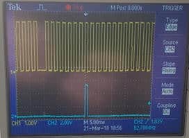
The oscilloscope image (see figure) shows the crank signal (top) in relation to the control signal of the coil (bottom). At the eighth tooth after the missing one, the control pulse to the coil is generated. During idling, the ignition is advanced by 10 degrees, which corresponds to 1 tooth. This therefore matches the 90 degrees (9 teeth) between the removed tooth and the actual top dead centre.
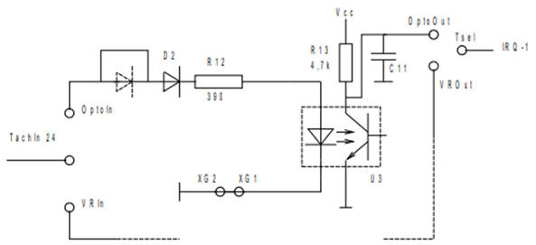
To assemble the Hall sensor circuit in the MegaSquirt, capacitor C11, resistors R12 and R13, diode D2 and opto-coupler U3 must be installed (see figure below). The signal from the Hall sensor enters the circuit in figure 105 at “Opto in”. Via the diode and resistor, the signal reaches the so-called opto-coupler. This component is indicated with a dashed outline. The opto-coupler is a small integrated circuit in which the LED on the left side, when lit, drives the phototransistor on the right side into conduction. The opto-coupler can be seen as a switch without mechanical or electrical connections between the drive and switching sections.
When the transistor in the opto-coupler is conducting, a small current can flow from Vcc to ground. At that moment, the voltage at “Opto Out” is 0 volts. If the transistor is not conducting, then there is no current and therefore no voltage drop across resistor R13. The voltage at “Opto Out” is then 5 volts.
By using an opto-coupler, a galvanic isolation is created between the diode and the phototransistor. Dangerous interference voltages are thus kept away from the microcontroller circuit, since the breakdown voltage is usually higher than 5 kV.
MAP sensor:
A MAP sensor (Manifold Absolute Pressure sensor) measures the pressure in the intake manifold. Using this pressure, together with engine speed and intake air temperature, the MegaSquirt calculates the amount of air entering the engine. On the Land Rover engine an absolute pressure (ambient air pressure) or vacuum will be measured. It is a naturally aspirated engine that draws in air by itself. Engines fitted with a turbocharger are subject to positive pressure in the intake manifold. The measuring range of a MAP sensor is usually between 0.2 and 1.1 bar.
The pressure in the intake manifold, together with the throttle opening angle (measured by the throttle position sensor) and the engine speed, can be used to determine the engine load. Because there is no MAF sensor (Manifold Air Flow), the amount of intake air is calculated on the basis of the engine data and the vacuum present in the intake manifold. A MAF sensor was not used because its signal is less reliable as it was not designed for this engine. Tuning the settings to the intake manifold characteristics is complex and requires many correction factors.
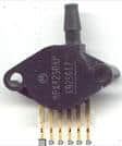
The MPX4250AP MAP sensor used is shown in the figure. The MegaSquirt PCB is standard equipped with connection options for this type of MAP sensor. This sensor is also supplied as standard in the kit. The amount of injected fuel depends, among other things, on the amount of air present, because the aim is a stoichiometric mixture ratio (14.68 kg of air to 1 kg of fuel). There was an option not to use either the MAF or the MAP sensor. The amount of intake air would then be determined according to so-called Alpha-N control. In this method, the position of the throttle valve is used as the decisive factor for the amount of air present. However, this is less accurate than using a MAP sensor, so this was not chosen. In this project, the throttle position sensor is used only for acceleration enrichment.
Coolant temperature sensor:
In the classic setup, no temperature sensors are yet present on the engine block. The engine is originally equipped with a bimetal switch, which serves to illuminate the dashboard warning light at an excessively high coolant temperature. Because the engine management system does in fact take into account the temperature of the coolant and intake air, it was decided to retrofit NTC resistors. An NTC resistor has a negative temperature coefficient. This means that the resistance value decreases as the temperature increases. As coolant temperature sensor, a sensor with a resistance value of 2.5 kilo-ohms at 25⁰ Celsius was chosen. With this sensor, the resistance variation is greatest in the most important temperature range. The characteristics of the NTC resistor must be mapped out in order to calculate an accurate temperature.
The change in resistance is greatest for a temperature change in the range between 0⁰C and 60⁰C. This can be seen from the shape of the characteristic; in the stated temperature range there is a resistance drop of about 5 kΩ, while at T ≥ 60⁰C the resistance hardly decreases. In some cases, it is desirable to measure temperatures above 60°C as well. To make this possible, the internal bias resistor can be switched at a certain temperature to a bias resistor of a different value. This produces two NTC characteristics. However, in this project the coolant temperature is used exclusively for cold start enrichment, which is hardly applied above 60°C.
The low temperatures are also the most interesting; this is where cold start enrichment takes place; the injector is actuated longer when the engine is cold. When the engine has warmed up sufficiently (T ≥ 60⁰C), the enrichment gradually decreases. From T = 90⁰C, the injection strategy follows the values set in the reference table. The reference table is a standard preset value. External factors, such as cold start enrichment at low temperature, form a correction factor on this standard value. In this phase, the MegaSquirt no longer takes the coolant temperature into account.
Lambda sensor:
A lambda sensor is mounted in the exhaust to measure the air/fuel ratio in the exhaust gases. The lambda sensor plays an important role in a later stage when “tuning” the engine management by filling in the AFR and VE tables. To understand the ideal mixture ratio and the purpose and necessity of enriching or leaning the mixture, the stoichiometric mixture ratio, enrichment and enleanment are first defined.
The stoichiometric mixture ratio indicates the ratio between air and fuel at which all oxygen in the air is used. This is the case at a ratio of 14.68:1 (rounded: 14.7 kg of air to 1 kg of petrol). We then speak of λ = 1.
Under different operating conditions, the lambda value can vary:
- Enrichment: λ < 1;
- Enleanment: λ > 1.
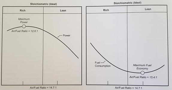
Enriching to λ = 0.8 means that a mixture ratio of 11.76 kg of air to 1 kg of petrol applies. There is therefore less air available to burn 1 kg of fuel. Enriching or leaning the mixture must always remain within the explosion limits. Enrichment occurs when the engine has to deliver more power. A richer mixture also provides cooling. A lean mixture, on the other hand, results in more favourable fuel consumption. The figure below shows two graphs indicating maximum power and lowest fuel consumption.
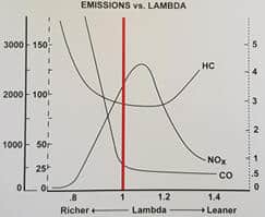
The lambda value affects not only power and fuel consumption, but also exhaust emissions. A richer mixture results in a lower NOx content, but also in higher CO and HC emissions. With a leaner mixture, the fuel particles are further apart, so combustion is no longer optimal; as a result, HC emissions also rise. The figure below shows the emissions in relation to the lambda value. When using a catalytic converter, it is desirable for the injection to alternate continuously between rich and lean. With a rich mixture, CO is formed as a result of an oxygen deficit, which the catalyst uses to reduce NOx. A lean mixture contains an excess of oxygen, which is used in the catalyst to oxidise CO and HC.
There are two types of lambda sensors: the narrowband sensor and the wideband sensor. The MegaSquirt supports both types. However, for setting up the VE table, a narrowband sensor is unsuitable, which is why a wideband sensor was chosen. The VE table is set by adjusting the VE values to the measured AFR. Although the VE values can initially be filled in through calculations and largely on the basis of the torque curve, the AFR quickly falls outside the range of the narrowband sensor. A wideband sensor offers a solution due to its large measuring range; it can measure an AFR between 8.0 and 1.4. With the engine running, the mixture composition will in almost all cases fall within this measuring range, which makes the wideband sensor suitable for setting up the VE table. Tuning without the wideband sensor is practically impossible.
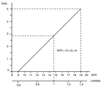
The MegaSquirt does not have an internal lambda controller. When the characteristics of the wideband sensor are known, they can be entered in a table in the TunerStudio program. In other cases, a wideband sensor with external controller is required. The output voltage is linearised by the external controller. The output voltage from the controller to the MegaSquirt is between 0 and 5 volts, with a linear relationship between the lambda value and the voltage. The voltage value is converted into a lambda value in the MegaSquirt. The figure shows the graph with the linear relationship.
Next: Actuators.