Towbar:
The towbar is usually fitted to the car afterwards. You can often choose between:
- A towbar with a fixed ball
- A towbar with a detachable ball
- An electrically retractable towbar
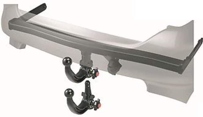
The towbar with a detachable ball is fitted most often (see the image). The towbar itself is often U-shaped and is bolted into the chassis rails of the car with its two ends. On other cars it may be a metal bar that is only mounted to the rear of the chassis rails.
Fitting the towbar is often quite simple. Once the rear bumper (and often also the rear light units) has been removed, the steel bumper beam can be removed. The towbar takes its place. It must then be attached to the bodywork with 4 or 6 bolts (consult the manufacturer for the tightening torques, this is very important!) Note that there are cars where you still have to drill holes in the body panels yourself!
Enough space must be left for the towball, the possible knob to detach / attach it, and of course the socket. This must also be accessible. Connecting the wiring is often more difficult. This is explained in the next chapter.
Wiring:
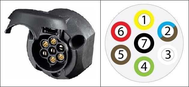
When purchasing a towbar, you can choose between a 7-pin or a 13-pin socket. The difference is that the 13-pin has a permanent and an ignition-switched positive feed, which is necessary to power, for example, a caravan’s fridge and interior lighting. This is described in detail (with pin assignments and colours) on the page terminal designations (socket).
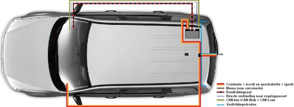
The images below show how the wiring runs for the standard 7-pin, the standard 13-pin, or the 13-pin CAN bus towbar wiring.
7-pin socket (standard):
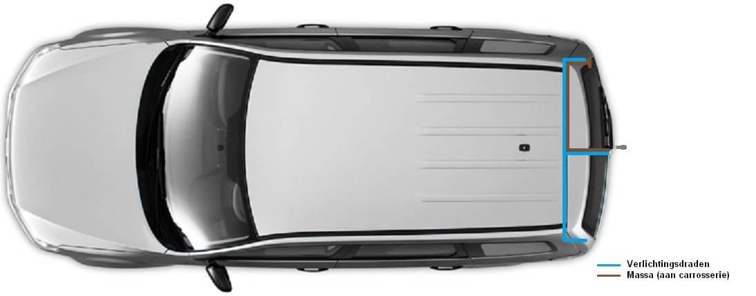
From the socket, a wiring loom runs directly to the rear lights. This is the simplest version. They are often ready-made kits designed specifically for a particular car type, so that the rear light connectors can be plugged into the wiring kit. The connectors from the wiring kit must then be plugged back into the rear lights. This way, the wiring does not need to be modified because only the connectors are clicked together in the correct way. This wiring can be installed very quickly and easily.
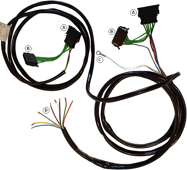
An example of such a standardised wiring loom can be seen in the image below.
The image shows the wiring loom of a Volkswagen Polo 9N. This wiring loom is installed between the standard connectors and the rear lights. Because the wiring loom is specifically designed for this Polo, all cables are the correct length and the wires are in the correct positions in the connectors. Below is an explanation of what the labels A to D stand for:
- A: This is where the rear light connectors are clicked in.
- B: These connectors are clicked into the rear lights.
- C: This is the ground cable and must be attached to a grounding point on the bodywork.
- D: These eight cables are for the 7-pin socket. One wire has the function of switching off the car’s rear fog light the moment the socket flap is opened. From connector A, the voltages are looped through to both connector B (to the rear lights) and the wires to the socket (D). With this wiring loom there is no permanent or ignition-switched positive feed. For this you need to fit a 13-pin socket and run two wires to the front of the car to connect them in the fuse box there.
13-pin socket (without CAN bus):
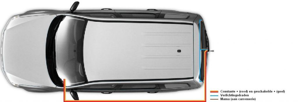
From the socket, cables run to the rear lights (as with the 7-pin). The rear lights directly control the trailer lighting. With a 13-pin socket there is also a permanent and an ignition-switched positive feed. These are connected to 12 volts via the fuse box (under the dashboard or otherwise under the bonnet). The permanent feed always has voltage, and the ignition-switched feed only gets voltage when the ignition is on terminal 15 (ignition on, or when the engine is running).
The wiring naturally runs inside (above the sill), but can also run forwards on the right-hand side. This depends on the vehicle type. On some cars the wiring also runs under the car from back to front.
| 1. | L | Left indicator | Yellow |
| 2. | 54G | Rear fog light (formerly permanent positive) | Brown / Blue |
| 3. | 31 | Ground | White |
| 4. | R | Right indicator | Green |
| 5. | 58R | Tail light, right side marker, number plate light | Brown |
| 6. | 54 | Brake lights | Red |
| 7. | 58L | Tail light, left side marker | Black |
Note! The pin assignments are standardised for the socket. Wire colours may vary by manufacturer. Always refer to the correct installation manual or factory data!
13-pin socket (with CAN bus):
The CAN bus version uses a control unit. This control unit controls the lighting (except the brake lights) of the trailer. From the BCM (Body Control Module, although each manufacturer has its own name) CAN bus wires run to the towbar control unit. Via these CAN bus wires, the information is sent indicating which lights must be on. An additional function of this CAN bus system is that it detects when a bulb is defective on the trailer. A warning will be given to the driver. This is constantly monitored by the trailer control unit, just like it normally is with defective lighting on the car itself nowadays.
The brake lights are controlled separately so that, in the event of a CAN bus fault with the trailer control unit, the brake lights still operate. The permanent and ignition-switched positive wires for the socket are also present. These now also serve as power supply for the trailer control unit.
The trailer control unit must always be coded using the brand’s diagnostic equipment.
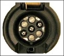
The 13-pin socket can be of the Jaeger type (the most common), or the Multicon. The Multicon West is a combination of a 7-pin and a 13-pin socket. A 7-pin plug from a trailer can be connected without any problems. Only the large inner contacts are used (no. 1 to 7). The outer contacts remain unused in that case. No adapter plug is needed. The outer contacts are only used when a 13-pin plug of the same type is connected.
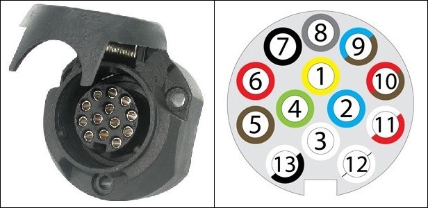
| 1. | L | Left indicator | Yellow |
| 2. | 54G | Rear fog light (formerly permanent positive) | Blue |
| 3. | 31 | Ground | White |
| 4. | R | Right indicator | Green |
| 5. | 58R | Tail light, right side marker, number plate light | Brown |
| 6. | 54 | Brake lights | Red |
| 7. | 58L | Tail light, left side marker | Black |
| 8. | 8 | Reversing light | Grey |
| 9. | 9 | Permanent positive (for example for interior lighting) | Brown/Blue |
| 10. | 10 | Ignition-switched positive (for example caravan battery or fridge) | Brown/Red |
| 11. | 11 | Empty position (optional ground) | White/Red |
| 12. | 12 | Empty position | – |
| 13. | 13 | Ground | Black/White |
Note! The pin assignments are standardised for the socket. Wire colours may vary by manufacturer. Always refer to the correct installation manual or factory data!
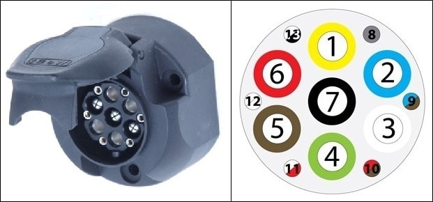
Multicon Feder:
The Multicon Feder is the predecessor of the Multicon West. The difference between them lies in the outer pin positions; 8 to 13. On the Multicon Feder (see image) these are flat contacts, while on the Multicon West they are round pins.
The ‘Feder’ connector is no longer used today, because it is more susceptible to faults than the ‘West’. With this socket it is also possible to connect a 7-pin plug from, for example, a simple trailer or a bicycle carrier.
Safety coupling and breakaway brake system:
To properly attach a trailer to the vehicle, it is legally required to use either a safety coupling or a breakaway brake system. If, due to a defect or incorrect handling, the trailer becomes detached from the towbar while driving, a safety system must be present that then comes into operation.
For trailers with a maximum mass (of the trailer including load) up to 1500 kg, using a safety coupling is sufficient. A safety coupling is nothing more than a thick steel cable that is attached to the trailer on one side and to the car on the other. If the trailer comes off the towbar while driving, the cable will ensure that the trailer continues to follow the car. The safety coupling does not operate the trailer’s brake.
When the maximum mass of the trailer is more than 1500 kg, it must be equipped with a breakaway brake system. The breakaway system consists of a steel cable that applies the trailer’s handbrake the moment it comes off the towbar while driving. The steel cable is thinner than with a safety coupling; the cable must break at a certain pulling force after the handbrake has been applied. The trailer then brakes independently without still being connected to the car. It is not permitted to have both a safety coupling and a breakaway brake system on one trailer. In an emergency, the trailer’s wheels could lock due to the breakaway system while it is still being pulled by the car via the safety coupling.
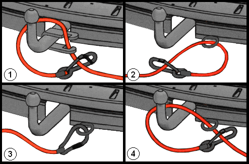
The images on the right show four possible ways in which the safety coupling and the breakaway brake system can be attached. The cable must always be connected to a fixed part of the towbar or the car’s body. In image 1 a special bracket is mounted on the towbar. The cable must be placed in a loop in the bracket.
In images 2, 3 and 4 the cable is attached to a fixed point on the car’s body. This fixed point can also be a hole in the towbar bracket into which the ball is mounted. An extra loop can also be placed around the towball here, as shown in image 4. It is prohibited to place the cable in a loop over the towball without this cable or loop being connected to a fixed part of the towbar or the body. The current fine for this is more than 150 euros.
On cars with an (electrically) retractable towbar, it is often not possible to mount a bracket as in image 1 above. The towball is often differently shaped; it is often square or rectangular. Often there is an eye on the ball itself where the cable can be attached, but experience shows that this is not always the case. The manufacturer, and in this case also the dealer, can supply accessories that fit the specific towball. For this, consult the brand dealer.
When fitting the cable, make sure that it cannot touch the ground while driving, even when the rear of the car compresses. Damage to the cable leads to an unreliable safety system.