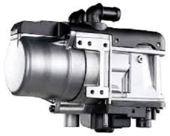
Introduction to auxiliary heater:
Passenger cars and commercial vehicles can be equipped with an auxiliary heater or electric auxiliary heating. Especially in countries with long periods of low temperatures, such as in Scandinavia, an auxiliary heater is very common. In the Netherlands we mainly see the auxiliary heater in exclusive passenger cars.
The auxiliary heater is connected to the fuel system and can operate with the engine switched off. It is often activated before a cold start of the engine. The advantages of using the auxiliary heater are:
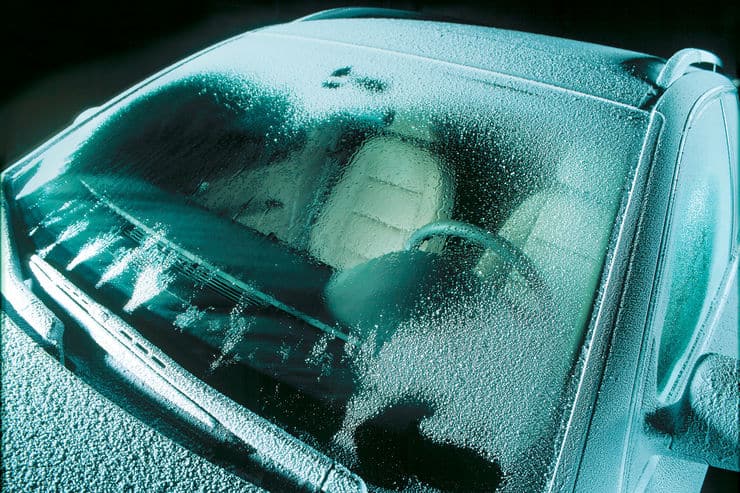
- The interior is at a higher temperature when getting in. This not only provides more comfort, it will also have melted any ice formation on the windows;
- The engine cooling system is preheated, which results in a better cold start. The engine reaches its operating temperature sooner. This not only benefits the service life (reduced wear), but also results in fewer harmful exhaust gases being emitted compared to a vehicle without this preheating.
An auxiliary heater can switch on automatically during a cold start at a low outside air temperature. During a cold start, the auxiliary heater can warm up a diesel engine in as little as 5 minutes. The auxiliary heater switches off automatically when the operating temperature is reached.
The auxiliary heater is connected to both the fuel and cooling systems. The fuel is ignited in the auxiliary heater and heats the coolant in the adjacent coolant channel.
We can find the auxiliary heater in various places in and around the car:
- In the engine compartment: the auxiliary heater may be installed behind the front bumper or in a wheel arch;
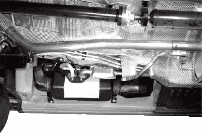
- Under the car: the auxiliary heater is often mounted under the car. The underbody protection shields it from dirt.
The following image shows the installation location in a Volkswagen Transporter (T5).
Operation of auxiliary heater:
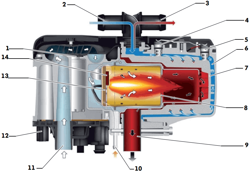
The fuel pump supplies the auxiliary heater with fuel. Via the fuel supply (number 10 in the image below), the fuel enters the so-called combustion housing. In this combustion housing, the fan (1) blows air from the intake duct (11) through the metal fleece to the combustion chamber and brings it into contact with the supplied fuel. As the glow plug (14) heats up, fuel in this metal fleece evaporates. The fuel ignites in the combustion chamber. At the moment the phototransistor in the flame monitor detects a stable flame in the glow tube, it reports this to the control unit (12), which immediately switches off the glow plug to prevent overheating. The exhaust gases from the combustion leave the auxiliary heater through the exhaust (10). The end of the exhaust pipe may exit at the level of the engine compartment or under the passenger compartment.
Legend:
- fan;
- coolant inlet;
- coolant outlet;
- temperature sensor;
- overheating sensor;
- water channel;
- heat exchanger;
- burners with combustion chamber and flame tube;
- exhaust of combustion gases;
- fuel supply;
- combustion air inlet;
- control unit;
- metal fleece;
- glow plug with flame monitoring.
Image source: Volkswagen AG.
The coolant supplied via the inlet duct (2) is guided through the water channels (6) along the combustion chamber. This creates a heat exchanger effect. The heated coolant leaves the auxiliary heater via the outlet (3) and flows to the heater core in the heater housing under the dashboard.
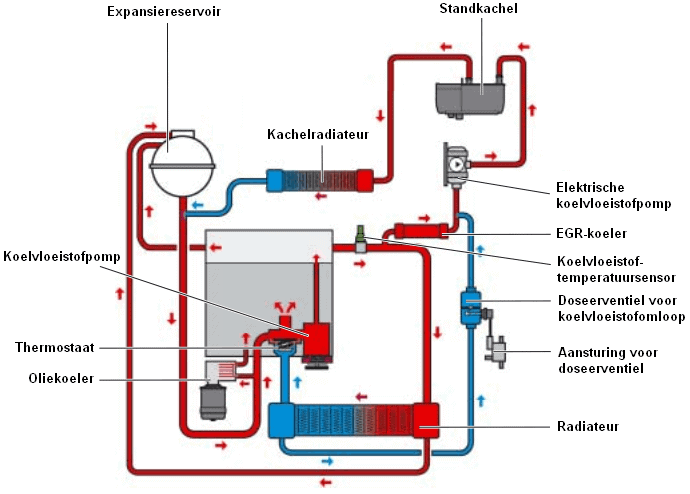
Cooling system of auxiliary heater:
The existing cooling system of the car has been extended with extra lines and components for the auxiliary heater. Here we find, among other things, an electric coolant pump that circulates coolant to the auxiliary heater when the engine is switched off. We also see that the coolant line from the auxiliary heater runs directly to the heater core: this warms up first. The blower, i.e. interior fan, will be activated to blow (cold) interior air through the warmed heater core into the interior.
After the heater core, the coolant line continues on to the combustion engine. In addition to the cooling system in the engine, the oil cooler will also warm up. When the engine is started, the engine oil will be heated more quickly by the oil cooler.
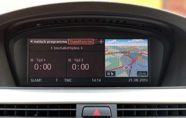
Activating the auxiliary heater:
The auxiliary heater can usually be activated manually with a remote control. Modern systems also offer the option of programming the activation of the auxiliary heater. Via the on-board computer, the switching times can be set so that the car is warm the next morning before departure.

Electric auxiliary heating:
Sometimes the combustion engine is not able to retain enough heat from the cooling system at low outside air temperatures. With a low engine load, the coolant temperature drops, causing the heater core and the air flowing through it for the heater to remain too cold. Electric auxiliary heating provides the solution.
As an example, we take the electric auxiliary heating of a Smart ForTwo 450.
The electric auxiliary heating is switched on when the following conditions are met:
- Outside air below 8 degrees Celsius;
- Coolant temperature below 85 degrees Celsius;
- Temperature selector lever in the maximum warm position;
- Blower switched on;
- Combustion engine running.
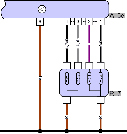
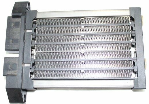
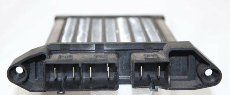
The auxiliary heater consists of four heating elements in a housing (R17) that are controlled by a control unit (A15e). As soon as current flows through a resistor, it heats up. The resistors are located in an air duct of the heater housing: the glowing resistor heats the passing air. The current through the resistors rises to 25 to 50 amperes, depending on the temperature. The inrush current is high, but the current when the resistors have warmed up decreases. After all, it takes less energy to keep the resistors warm than to heat them up.
The maximum power is approximately 900 watts at 14 volts.
The two images below show the electric heating element.
Related page: