Introduction:
The climate in the car can be optimally adjusted with today’s systems. When it is cold, the interior can be heated in several ways. This heat comes from the engine’s waste heat. The aim is to maintain as constant and comfortable a temperature as possible. At high outside air temperatures it is pleasant when cool air is blown into the interior. In cars without air conditioning this is simply the outside air, but in cars with air conditioning this outside air is first cooled considerably before being blown into the interior. If the temperature is too high, loss of concentration, slower reactions and fatigue can occur.
Air conditioning also affects the humidity in the interior; it decreases. At too high a humidity you may feel stuffy and oppressed, and at too low a humidity you may get a dry throat and dry eyes. The most comfortable climate is a temperature between 20 and 23 degrees, with a humidity between 30 and 60%, and of course with filtered air by means of a cabin filter.
Ventilation control:
Due to variations in the outside temperature or in the vehicle speed, the temperature inside the car changes. To maintain the correct temperature, the heater and ventilation settings must be adjusted regularly with manual heating. Cars with automatic temperature control do not have this problem; they automatically adjust fan speed and temperature. The control unit ensures that the set temperature is maintained. When, for example, 20 degrees Celsius is set and in the meantime a window has been briefly opened while it is cold outside, the interior temperature sensors will detect that the interior temperature has dropped. The heating temperature will rise (to, for example, 24 degrees) and the ventilation speed will increase. As soon as the interior has again reached the temperature of 20 degrees Celsius, the fan speed and outlet temperature are reduced again.
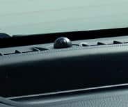
The sun sensor on the dashboard also influences the speed of the interior blower. The light intensity is measured by means of the ultraviolet radiation in the sunlight. In bright sunshine the interior blower will blow a larger quantity of cold air into the cabin. The sun sensor can be recognised by the little dome, usually located in the middle at the top of the dashboard. The image shows a sun sensor.
Temperature control:
The temperature in the interior can be kept constant in two ways; namely by using:
- Mixed air control: The cold and warm air are mixed together in the heater housing by means of heater flaps. The cold air is the outside air temperature and the warm air is as hot as possible (heated to the maximum by the coolant). By opening the warm-air flap a bit further each time, a little more warm air is added to the outside air. More information about the heater housing is described further down the page.
- Coolant control: By actuating heater valves electronically, the coolant flow through the heater radiator is altered. The outside air flows through the heater radiator. The air is heated as a result. The air temperature therefore depends on the coolant temperature in the heater radiator. More information about the heater radiator is described further down the page.
- Evaporator: The evaporator is a component of the air conditioning system and is described on a separate page. By allowing the warm outside air to flow through the cold evaporator, this air is cooled down.
The interior blower must blow the air through the heater housing, heater radiator and / or evaporator in order to bring the air to the desired temperature and then allow it to flow into the interior.
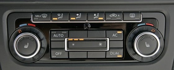
Vehicles equipped with a dual-zone climate system have an adapted heater housing that allows the outlet temperatures on the left and right to differ.
The following image shows a dual-zone climate control system in which the outlet temperature on the driver’s side is 21 degrees Celsius and on the passenger side 23 degrees.
It is possible for the rear passengers to also have one or two separate climate zone(s) with a rotary knob or display to set the temperature in two additional zones. In that case the heater housing contains extra channels for the mixed-air control.
Heater housing:
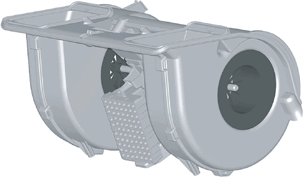
The heater housing is shown below. The interior blower is mounted below the heater radiator. The ventilation air enters at the side of the interior blower and is blown at the top through the heater radiator and the air conditioning evaporator. The heater housing is located in the middle under the dashboard and can in principle only be removed if the complete dashboard has been taken out.
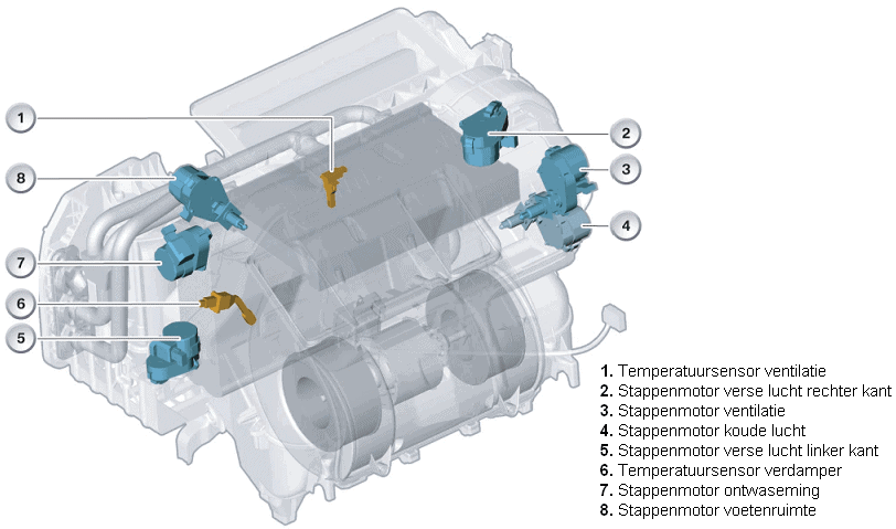
In the image above a transparent heater housing with several stepper motors can be seen. The stepper motors operate flaps that control the airflow and the air temperature. In the image below, the airflow through a heater housing is shown, including the flaps operated by the stepper motors.
The interior blower draws in outside air through the intake duct. The end of this intake duct is usually located under the bonnet, behind the plenum panel. The interior blower blows the drawn-in air, if the car is equipped with air conditioning, through the evaporator. In the evaporator, the moisture and heat are extracted from the outside air, so that dry and cooled air enters the heater radiator. When the air conditioning is switched off, the air also flows through the evaporator, but it will not undergo any change in temperature or humidity.
The temperature of the heater radiator affects the heating of the air; valves in the coolant circuit provide an adjusted flow rate; a lower coolant flow will cause less heating of the air. From the heater radiator the air reaches at least three air control flaps: one to the windscreen, one to the ventilation grilles in the dashboard and one to the footwell. The position of the flap determines how much air is blown to the respective outlets.
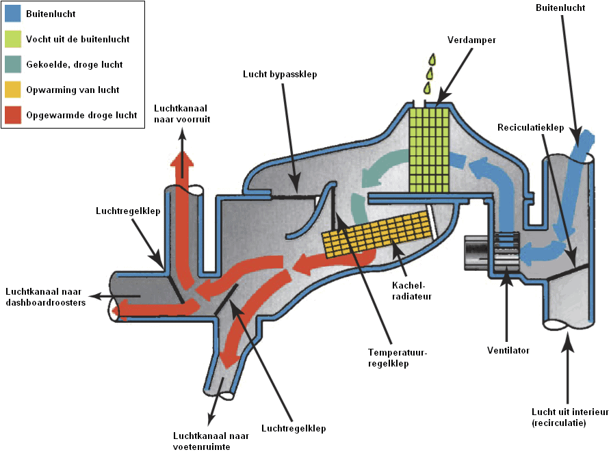
The operation of the air control flaps, the temperature control flap, the air bypass flap and the recirculation flap can be carried out manually. In that case there is a physical connection with a Bowden cable between the sliders or knobs on the dashboard and the flaps. Nowadays we almost only see electronically controlled flaps: a control unit operates the stepper motors.
An electronically controlled ventilation system often has more features than a manually operated system with cables:
- multiple temperature zones: on the driver’s side the air control flaps and the temperature control flap can be operated independently of the passenger side. In this case the flaps are implemented in duplicate. In luxury cars there are even up to four adjustable zones: this doubles the number of flaps and air ducts in the same heater housing;
- a MAX setting to allow the air conditioning to operate at maximum capacity: in the MAX setting the air bypass flap opens and the temperature control flap closes: only cooled air enters the distribution housing with the air control flaps. The recirculation flap will also close off the supply of outside air and draw in the already cooled air from the interior via the blower and cool it further;
- automatic opening and closing of the recirculation flap when the air quality sensor registers harmful substances in the drawn-in outside air.
Interior blower:
An interior blower is shown below. The interior blower is also called the “heater motor” or “blower motor”. In the middle of the interior blower are the impeller blades, which ensure that air is blown into the interior. The ventilation air is drawn in at the top of the motor and led via the ducts at the side to the heater radiator. The heater radiator is mounted directly after the interior blower in the heater housing.
On the heater motor page the operation and the different control methods are explained.
Heater radiator and heater valve:
The heater radiator provides the heating of the air that is blown into the interior. The heater radiator consists of two pipes (a supply and a return) which are split into channels with fins placed between them. The fins provide a larger heat-exchange surface.
The heater radiator works in the same way as the radiator at the front of the car as a heat exchanger. The cold air flowing through the fins is heated by the coolant that flows through the channels along the fins. The heat from the coolant is transferred to the airflow. The heated air enters the vehicle interior; this is the heater that is activated by the occupants. Because the warm air that the interior blower blows into the interior depends on the coolant temperature, it is logical that the heater is still cold immediately after starting the engine. The heater is only fully effective when the engine is at operating temperature.
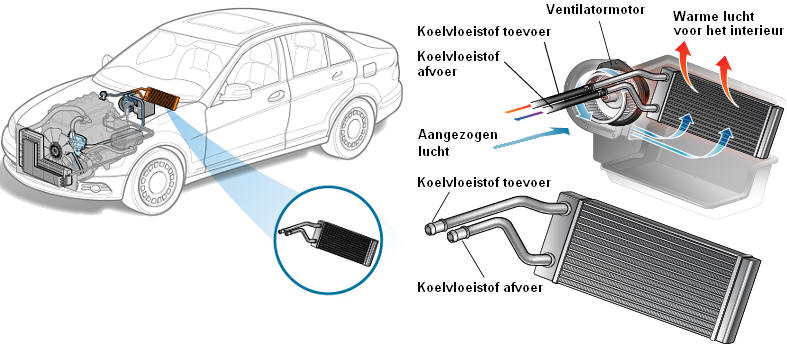
The occupants can set the heater warmer or colder. By operating the heater, the opening angle of the heater valve changes. The heater valve regulates the amount of coolant flowing through the heater radiator. The size of the coolant flow ultimately determines the air temperature.
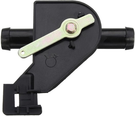
The image below shows a heater valve with pipes on both sides over which the coolant hoses are slid. In the middle of these pipes there is a rotating flap which, depending on the opening angle, blocks or allows the coolant flow. The flap is operated by the lever, which can also be seen in this image. The lever can move up to 90 degrees; in the end positions the flap is fully open or closed. A Bowden cable to the heater control unit (mechanical) or an electric / stepper motor (electrical) is connected to this lever. More on this later.
The control principles of the heater valve are described below:
Heater valve fully open:
- Large coolant flow.
- The coolant is not easily cooled by the airflow.
- The material of the heater radiator remains very hot.
- The air blown into the interior is therefore also warm.
Heater valve partially open or closed:
- Small or no coolant flow.
- The coolant is therefore cooled more easily by the airflow.
- The material of the heater radiator cools down.
- The air blown into the interior is lukewarm or cold, because the outside air temperature has hardly been affected.
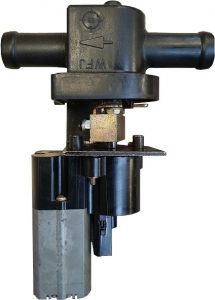
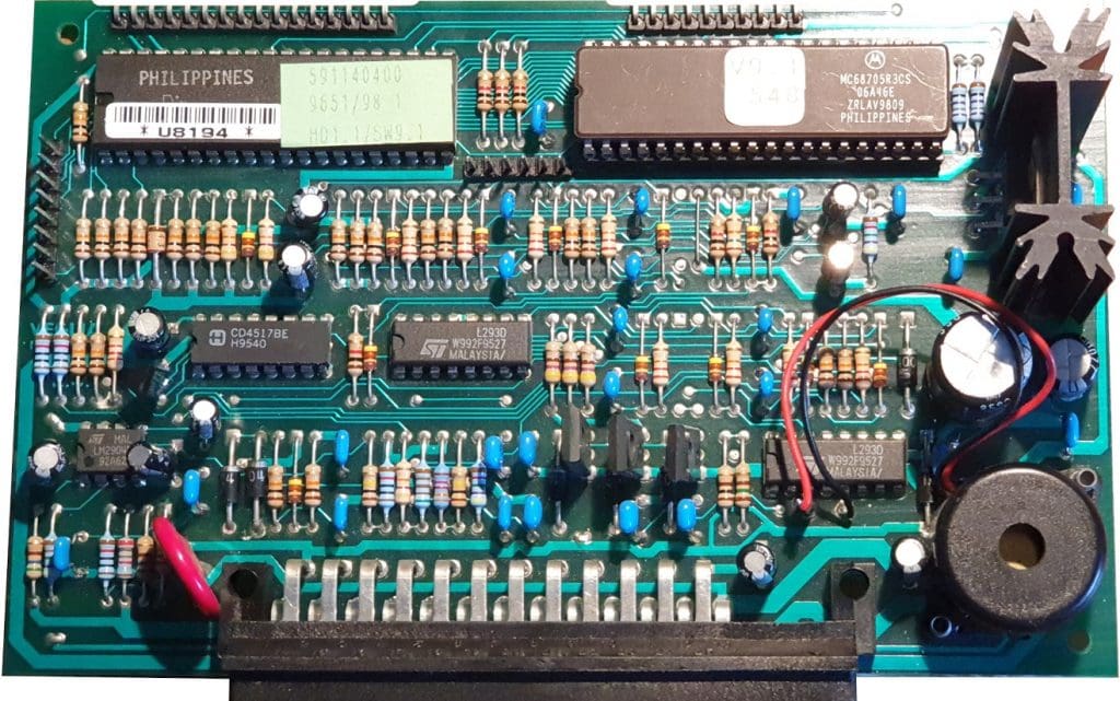
The images below show the components:
- The basic operating principle of the actuator (left);
- The heater valve and actuator in installed condition (centre);
- The ECU of the climate control system (right).
The respective actuator and ECU come from a 2001 Maserati Quattroporte. The actuator is a DC electric motor type with carbon brushes. It is controlled by a duty cycle from an ECU. Via several gear stages, the electric motor drives both the output shaft and the wiper that moves over the contact disc. The disc is supplied with a voltage of 5 volts and ground. Depending on the position of the wiper, a signal is sent to the ECU that determines the position of the output shaft, and thus the heater valve. In the current position, the signal voltage is 4.5 volts. When the output shaft and wiper rotate a few degrees counterclockwise, the signal voltage drops to 4.4 volts or lower. In the end positions, the signal voltage will be between 0.5 and 4.5 volts.

The ECU controls the heater valve until the mechanical end stop is reached. Due to the low torque of the electric motor, the rotation is stopped by this end stop and at the same time the signal voltage of the wiper on the contact plate remains constant. The ECU will end the control.
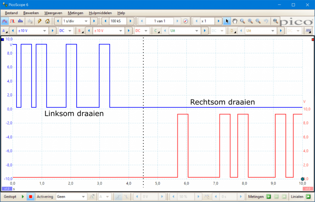
The electric motor is supplied with a supply voltage and ground. These are controlled via PWM by the ECU. The following oscilloscope image shows the control signals measured on the positive and negative terminals of the electric motor during clockwise and counterclockwise rotation.
- Counterclockwise rotation: the ECU sends a square-wave signal to the positive terminal of the electric motor. The ground is a constant 0 volts;
- Clockwise rotation: the polarity of the electric motor is reversed.
It may occur that the little shaft in a heater valve starts to move more heavily due to age. Because of this mechanical resistance, the ECU may “think” that the end stop has been reached. The control is then terminated. A new article will be published soon in which a fault in the control was present with the ECU and actuator motor shown above. After diagnosis and repair of the circuit board, the system worked properly again. The symptoms, cause and solution will be clarified by means of images.
In addition to this version with DC motor and PWM control, many heater flaps and heater valves are controlled by a stepper motor.
At the moment the heater is activated directly in winter and the interior fan is set to position 4, the engine will also reach operating temperature more slowly. This is because the passing air cools the coolant again. That is not desirable, as we naturally want the engine to warm up as quickly as possible. It is therefore advisable to activate the heater only after having driven a few kilometres.
With a parking heater or electric auxiliary heater, the heater radiator and the cooling system of the combustion engine can be brought up to temperature more quickly.
Ventilation ducts:
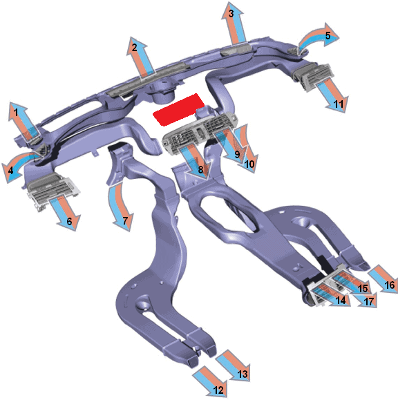
In the image below, the ventilation ducts and outlets are shown. Normally this is not visible, because the dashboard, centre console and carpeting are mounted over them. The stepper motors of the heater flaps in the heater housing control the airflow to the different directions (to the windscreen, to the left or right ventilation grilles, or to the footwells). There is a constant ventilation flow to the rear compartment. The rear ventilation grilles in the centre console can be closed mechanically.
Numbers 1, 2, 3: Air outlet to the windscreen (including for windscreen demisting / Defrost)
Numbers 4, 5: Demisting of both side windows of the front doors
Numbers 6, 8, 9, 11: Ventilation grilles for driver and passenger compartments
Numbers 7, 10: Air outlets for the footwells of the driver and passenger compartments
Numbers 12, 13, 16, 17: Air outlets for the rear passengers’ footwells
Numbers 14, 15: Ventilation grilles in the centre console for the rear passengers