Introduction:
Electric motors are being used in more and more places in the car. In an electric motor, electric current is converted into motion and heat. We find an electric motor in the mirror and seat adjustment, but also as a wiper motor in the wiper mechanism or as a starter motor. These electric motors operate at a voltage of 12 to 14 volts. On this page we limit ourselves to the electric motors in the interior and exterior.
Electric motors also provide the (partly) electric drive in hybrid and fully electric vehicles. This type of electric motor is discussed on the page: HV electric motors.
The DC electric motors can be divided into:
- Electric motor with carbon brushes (electromagnetic field and armature)
- Series-wound electric motors;
- Shunt (parallel-wound) electric motors;
- Brushless electric motors.
Operating principle of electric motors:
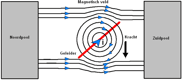
In an electric motor, electric current is converted into a rotating motion. The motion is created because two magnetic poles attract or repel each other:
- A north pole and south pole attract each other;
- Two north poles repel each other;
- Two south poles repel each other.
A magnet has both a north and a south pole with opposite charges. When that magnet is broken in half, you do not suddenly have two separate poles, but two new magnets, each again with a north and a south pole.
Multiple magnetic poles (north and south) are fixed to the housing. A magnetic field exists between the north and south poles. The output shaft (the armature) rotates as a result of changes in the magnetic field.
In an electric motor, using (usually) permanent magnets, or alternatively electromagnets, two like poles are constantly positioned opposite each other. Because like poles repel each other, motion is created.
DC electric motor with carbon brushes:
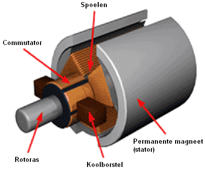
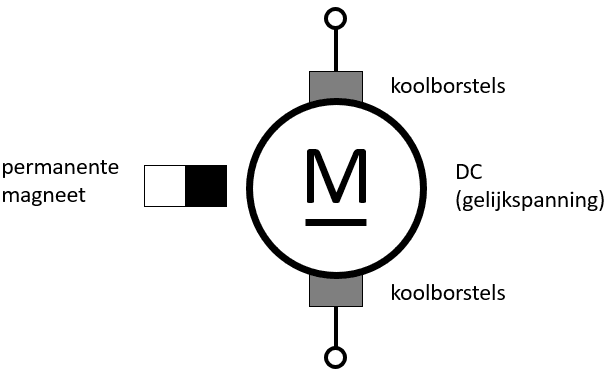
Almost all electric motors in automotive engineering are designed as DC motors with permanent magnets and carbon brushes. In this type of electric motor we find the following magnets:
- Permanent magnets (one north pole and one south pole): a stationary magnetic field exists between them;
- Coils: an electromagnetic field is generated in them. In the coils, the rotating electromagnetic field is generated.
The permanent magnets are located to the left and right of the rotor and consist of one north pole and one south pole. Between this north and south pole there is a stationary magnetic field that does not change when the electric motor is operating or stationary.
In the coils, a rotating electromagnetic field is generated as soon as current flows through them. The current is supplied to and removed from the coils via the commutator by the carbon brushes.
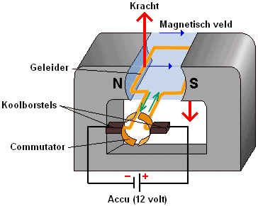
Reversing the direction of current takes place by means of commutation: two carbon brushes slide over the commutator, which consists of a positive and a negative side. The carbon brush on the positive side carries the current to the conductor (green arrows in the image). The current leaves the conductor via the carbon brush on the negative side. The current flowing through the conductor generates an electromagnetic field.
Between the magnetism that is created in the armature (the conductor) and the field (the permanent magnets), a force arises (red arrows in the image). This force causes the armature and the commutator to rotate about their axis. The carbon brushes then contact the other section of the commutator, reversing the current direction in the armature. The magnetic field and the force are built up in the same direction, so that the armature again rotates about its axis.
We can change the direction of rotation of the electric motor (i.e. the armature) by reversing the positive and negative connections of the carbon brushes.
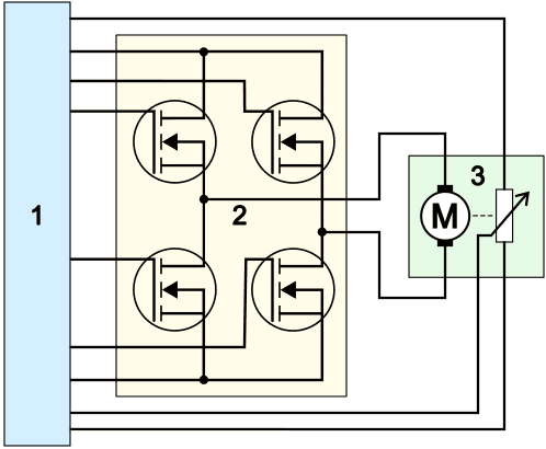
Reversing positive and negative can be achieved through commutation (as explained above), or can be implemented by means of an H-bridge in an ECU circuit.
- The ECU (1) controls two of the four transistors or FETs (4) at the same time;
- The FETs (2) supply the electric motor (3) with positive and ground. Depending on which two FETs are switched on, the upper carbon brush is positive and the lower one is ground, or vice versa;
- The potentiometer next to the electric motor registers the position and direction of rotation. Not all electric motors are equipped with a potentiometer.
See the page H-bridge for the possible designs and switching methods of the H-bridge.
DC electric motor as shunt (parallel) or series motor:
Electric motors are used in vehicles in different ways, depending on the requirements for torque, speed and efficiency. We distinguish two types of DC motors: the shunt (parallel) motor and the series motor. These are explained below.
Shunt (parallel) motor:
In a shunt (parallel) motor, the field windings are connected in parallel with the armature winding. As a result, the current through the field winding remains relatively constant, regardless of the load on the motor. This results in a stable magnetic flux and an almost constant speed, even with varying loads. The force produced by the motor is proportional to the current through the armature winding, which ensures smooth operation at different speeds.
A shunt motor is used in systems where controlled speed and long-term operation are required, such as an electric cooling fan, fuel pump, wiper motor or electric water pump.
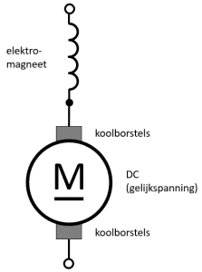
Series motor:
In a series motor, the field windings are connected in series with the armature winding, so the same current flows through both windings. The greater the current flowing through the motor, the stronger the magnetic field becomes. This means that the magnetic flux increases as the load becomes greater, which leads to a higher torque. As a result, a series motor performs particularly well at high loads. However, the speed of the motor decreases with an increasing load, because the additional magnetic flux increases the torque but at the same time lowers the speed.
When the motor is switched on, a strong magnetic flux is created because the current through both the field and the armature winding is high. This provides a high starting torque. This makes the series motor very suitable as a starter motor, especially under severe conditions, such as with a cold engine or a low battery voltage. Other applications of series motors are: electric winches, drive systems of forklift trucks.
A series motor has a higher starting torque than a shunt (parallel) motor for the following reasons:
- the starting torque is immediately high when the electric motor is still at a standstill;
- no back EMF has yet been generated from standstill,
- the current is at its maximum at the moment it is switched on.
The starting torque of a shunt (parallel) motor and a series motor can be compared with each other. The formula for calculating the starting torque of an electric motor is:
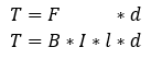
T = torque [Nm]
F = Lorentz force [N]
B = magnetic flux in Tesla [wb/m2]
I = current [Ampere]
l = length of copper wire [m]
d = diameter of armature [m]
To substitute actual values into the formula T = B * I * l * d, we can make assumptions based on typical values for shunt and series motors in vehicles. A series motor initially has a higher current (I) and therefore a higher magnetic flux (B) than a shunt motor. When the other variables (length of the copper wire and the diameter of the armature) are the same, we can compare the generated torque of the two motors.
First, the table with the properties of both motors is shown.
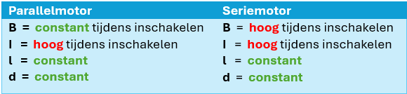
The above table shows that the I (current) is high for both motors, but that the B (magnetic flux) of the series motor is high during switch-on, while that of the shunt motor remains constant.
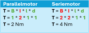
If we reason this out in a formula, using 1 to represent constant and 2 to represent high, we see that the torque generated by the series motor is higher:

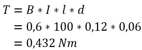
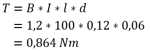
If you prefer to work with numbers instead of reasoning with 1 or 2 for constant or high, you can look at the formulas filled in below, in which the shunt and series motors are compared. In these, the magnetic flux (B) and the starting torque (I) are variables, and l and d are equal. The torque of the series motor is also significantly higher in this case.
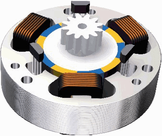
Brushless DC electric motor:
The brushless direct current motor (DC) is a synchronous motor. The electrical control has taken the place of the carbon brushes. This type of electric motor is very similar to the synchronous AC motor with permanent magnets, as used in the drivetrain of electric vehicles. The main difference between the two motors is the control method: the AC motor is controlled with a modulated sinusoidal alternating voltage and the DC motor with a block voltage.
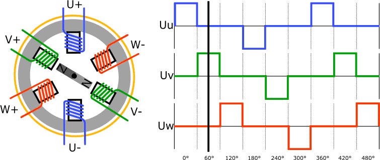
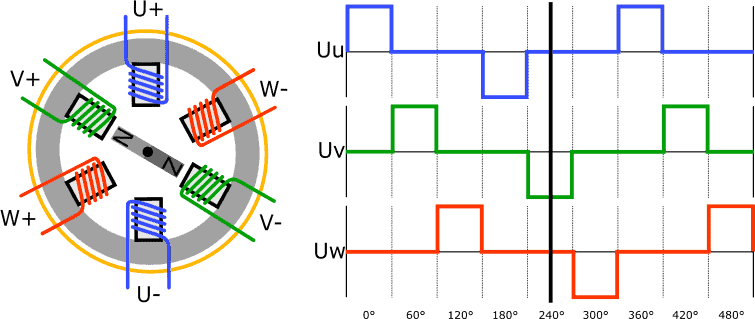
The stator often contains three or six windings (U, V and W) and the rotor is a permanent magnet. The image below shows the schematic design of the DC motor, along with the voltage curve through the three windings. In reality, several Hall sensors are placed between the poles to determine the rotor position.
The control unit determines, based on the rotor position, which windings it must energize.
In the next image, the U+ winding is energized. The way the winding is wound around the pole determines whether it becomes a north or south pole. In this example, U+ is the north pole and U- the south pole.
The rotor is designed as a permanent magnet. As already described in the previous paragraphs, the rotor positions or rotates as a result of a changing magnetic field through the windings.

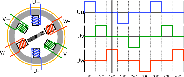
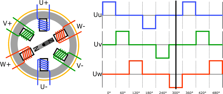
To make the rotor rotate counterclockwise from the position shown in the previous image, the V windings are energized.
The V+ becomes the north pole, V- the south pole. The rotor with permanent magnet rotates;
the north and south poles attract each other, as do the south and north poles on the other side of the magnet.
Now the W windings are energized to rotate the rotor another 60 degrees.
The W+ winding becomes a north pole and W- the south pole. The rotor rotates and takes up its new position.
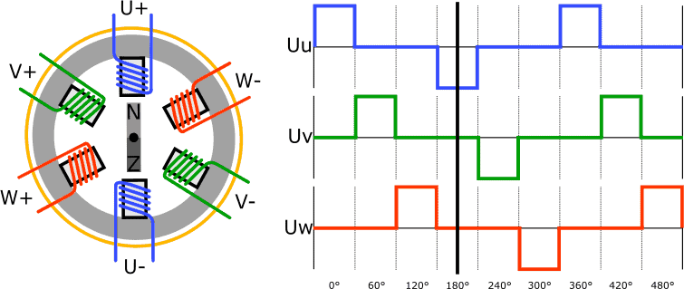
The rotor in the next image has rotated 180 degrees since the first situation; in the first image the south pole was facing upwards; now it is the north pole.
The polarity of the U+ winding and the U- winding has been reversed, causing the current to flow in the opposite direction through the windings. This has made U+ a south pole, and U- a north pole.
The rotor with permanent magnet rotates further due to the change in the magnetic field.
To rotate the rotor another 60 degrees, V- is made a north pole and V+ a south pole. The rotor takes up the new position.
Once again, the rotor rotates 60 degrees as a result of the change in the magnetic field in the windings:
The W- winding is the north pole and W+ the south pole.
In the six situations described above, there are constantly two windings energized at the same time. We also often find brushless DC motors with three windings instead of six. With three windings, the U, V and W windings are also energized one after another, but there is no change in polarity.
The brushless DC motor is a powerful motor that is suitable for applications where a high torque is required for starting, medium speed as well as high speeds. The brushless DC motor and the stepper motor are often confused. This is understandable, because the operation and control of the motors have many similarities: both motors are driven by creating a magnetic field between the windings and the rotor with permanent magnets. Nevertheless, in addition to the terminology, the two motors have essential differences mainly in their application and the corresponding choice of materials.
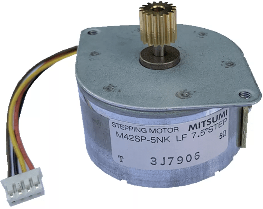
The stepper motor is in fact a brushless DC motor, but is used in a different area. Whereas the DC motor is mainly used for continuous running at high speeds, we see the stepper motor in applications where adjustment to an exact position is the most important.
The control of the DC motor shown takes place at every 60° rotation of the rotor. This could possibly be reduced to 30° if we energize four windings at the same time between each control step, thus obtaining an intermediate position. However, a stepper motor is capable of adjusting in steps from 1.8° down to 0.9°. This shows all the more that the stepper motor is suitable for very precise positions.
You can find the different designs, the control methods by the ECU and the applications on the stepper motor page.