H-bridge:
A brushed electric motor can be connected to components that need to move back and forth. The electric motor must be able to rotate in two directions, so that it can, for example, both open and close a valve.
- To make an electric motor rotate, one of the brushes is connected to positive and the other to ground;
- To make the electric motor rotate in the opposite direction, the polarity can be reversed. By swapping positive and negative, the direction of rotation also changes.
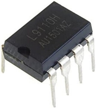
To enable the change of direction of rotation, a so‑called H-bridge is used. The ECU controls two transistors or FETs in an H-bridge to provide the electric motor with power and ground. Almost every type of electric motor controlled by an ECU is supplied with voltage and current by means of an H-bridge. Examples include the electric motor of an EGR valve, electronic throttle body on a petrol engine, mirror glass adjustment, window motor, seat adjustment, steering wheel adjustment, heater flaps (blend flap and fresh air quantity flap). The following image shows the H-bridge IC DIL (Dual In Line) with eight pins, type: L9110H.
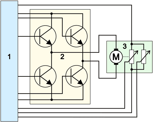
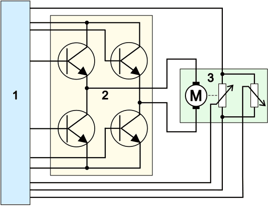
The diagrams below show an ECU (1) H-bridge (2) with transistors (left) or FETs (right) and an actuator motor with potentiometer (3).
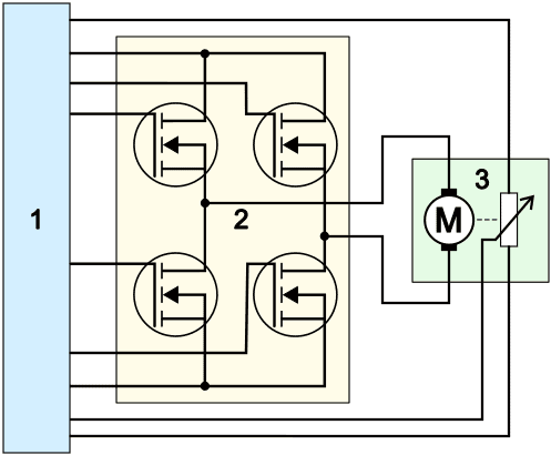
The ECU controls the appropriate transistors or FETs to bring them into conduction. Below, for each type of H-bridge, the two situations are illustrated to make the electric motor rotate clockwise or counterclockwise. The two upper transistors or FETs switch through the positive supply and the two lower ones the ground. The green wires are the control wires from the ECU (1) to bring the transistors or FETs in the H-bridge into conduction. The control of both types of H-bridges therefore shows many similarities.
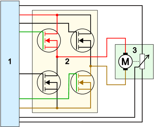
H-bridge with transistors:
- To rotate the electric motor clockwise: the upper left and lower right transistors are brought into conduction;
- To rotate the electric motor counterclockwise: the upper right and lower left transistors are brought into conduction.
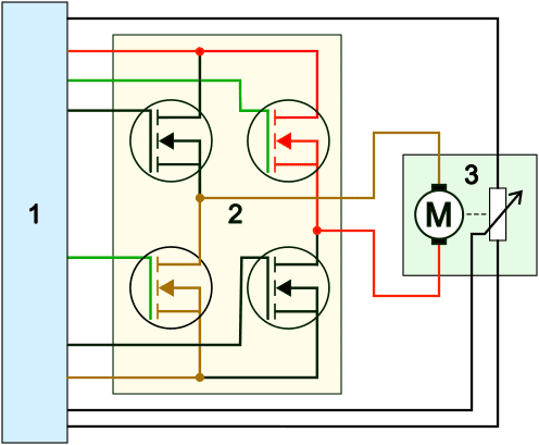
H-bridge with FETs:
- To rotate the electric motor clockwise: the upper left and lower right FETs are brought into conduction;
- To rotate the electric motor counterclockwise: the upper right and lower left FETs are brought into conduction.
Position sensor:
The ECU controls the appropriate transistors or FETs to rotate the electric motor in the correct direction. In the examples above, a position sensor is also visible next to the electric motor. This position sensor (the potentiometer) feeds back the position and direction of rotation of the electric motor to the ECU. Because this allows the ECU to know the position of the electric motor, the ECU can move the motor precisely to the position in which it has been calibrated. An example is a heater flap in the heater housing of the fully automatic climate control system. The heater flap can be fully open (100%) or fully closed (0%), but can also be opened to two-thirds (66%). Because positions are known in the ECU via learning the flap end stops, the ECU can control the electric motor until the signal from the potentiometer indicates the desired position. The ECU then stops driving it.
Throttle actuator motor:
In the first paragraph, the throttle control was mentioned in which the H-bridge controls the electric motor. The difference from the images shown earlier is the dual potentiometer. In the two images below we see the dual potentiometers of the throttle actuator motor.
- Potentiometers with wipers pointing upwards: both signals change in the same way, but at a different voltage level;
- Potentiometers with wipers opposite to each other: signals are mirrored. When one signal rises as the throttle valve opens, the other signal drops.
Related pages: