Introduction:
Every petrol engine has a throttle valve. The throttle valve controls the amount of air entering the cylinder. Diesel engines also have a throttle valve, but it is always fully open when the engine is running. That is because a diesel engine runs with an excess of air. The throttle valve on diesel engines only serves to let the engine shut down smoothly; when the valve closes, the air supply is cut off. The engine then stalls immediately. The fuel supply is also stopped. In a diesel engine this is also called the choke valve instead of the throttle valve. In fact, a throttle valve in a petrol engine is also a choke valve: the air is restricted under all conditions except full load.
The following chapters about the single-point and multi-point injection systems naturally relate to petrol engines.
Throttle valve in a single-point injection system:
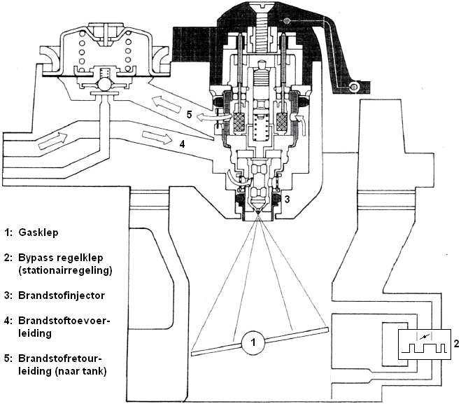
In engines with single injection (single-point injection system) one injector is mounted in front of the throttle valve. This injector sprays the fuel directly onto the throttle valve. This technology is old and is no longer used in modern cars. That is because this system has a number of disadvantages. As the injector sprays onto the throttle valve, it mixes with the air at that point. The intake manifold is distributed over four or more cylinders. The amount of fuel will not always be exactly the same in all cylinders. Cylinder 1, for example, receives the most fuel in the intake air, while cylinder 4 receives much less. As a result, the system is not, or hardly, controllable. The use of single-point injection is therefore unsuitable for meeting current environmental standards.
Nowadays, multiple injectors are used that inject exactly the same amount of fuel per cylinder. The quantity can even be controlled per cylinder. We call this the multi-point injection system.
Throttle valve in a multi-point injection system:
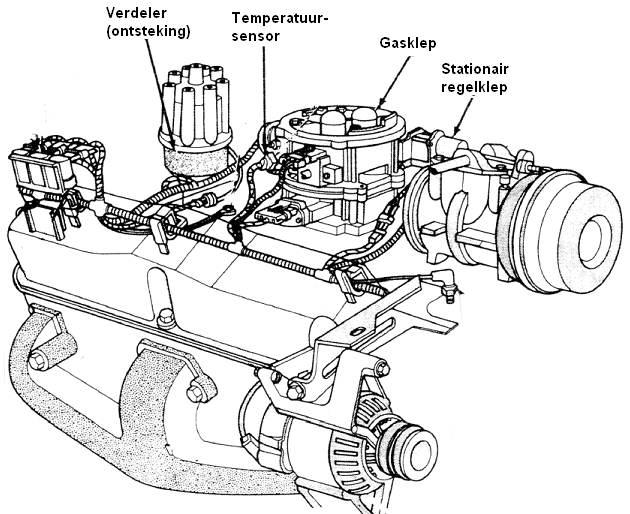
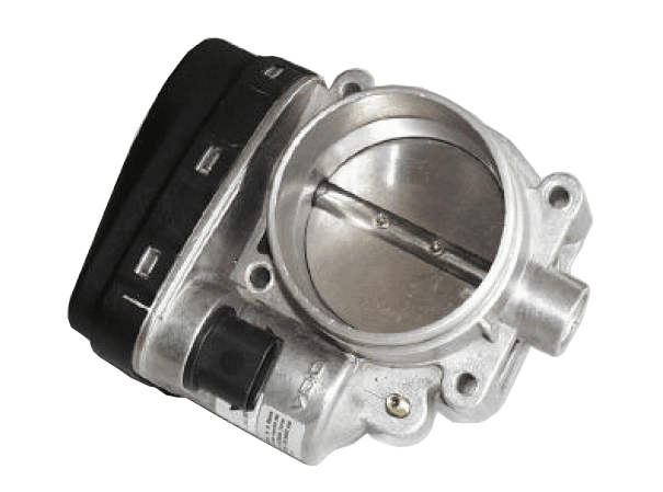
In engines with multi-point injection (multi-point injection system), with indirect injection the injectors are mounted in the intake manifold after the throttle valve. The injectors spray onto the engine’s intake valves. With direct injection, the injectors spray directly into the combustion chamber. In both indirect and direct injected engines, a throttle body is fitted as shown below. Exceptions are engines with Valvetronic (BMW) and Multi-air (Fiat). The throttle body is mounted between the intake manifold and the duct with the mass air flow sensor. It can be actuated electrically by means of an electronic accelerator pedal (drive by wire) or with a throttle cable (Bowden cable).
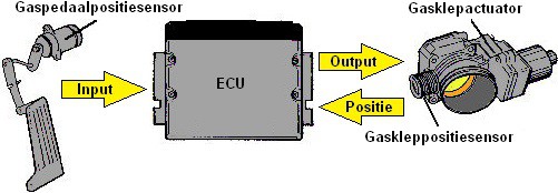
The engine management systems used today employ throttle position control. An actuator motor on the throttle valve allows the position of the throttle valve to be changed. This may be for cruise control or for idle speed control. Potentiometers measure the position of the throttle valve. The engine control unit (the ECU) receives the values from the potentiometers and can then control the actuators to open or close the throttle valve further.
Idle speed control:
To accelerate, the accelerator pedal is pressed. The throttle valve opens so that a larger quantity of air can be drawn in. During deceleration or idling, the accelerator pedal is not operated; here the throttle valve is closed. To obtain an air passage nonetheless, an idle speed control system is used. The idle speed is kept as low as possible by the engine management system. The lower the idle speed, the lower the fuel consumption and engine wear. The idle speed must not be too low; this causes an irregularly running engine and there is a risk that it will stall. The desired idle speed is not always the same. The temperature of the intake air, the air conditioning being switched on, the position of the clutch pedal or the automatic transmission selector lever all influence the idle speed control. Stabilisation of the speed control can be achieved in different ways:
- charge control. This is used most often, in combination with adjusting the ignition timing.
- changing the air-fuel mixture composition. This has a negative effect on exhaust emissions and the control range is limited.
- adjusting the ignition timing. This also has a negative effect on emissions, but does allow extremely fast control.
- adjusting the valve timing. This provides an additional control option on top of an existing charge control.
With charge control, a by-pass valve is used that allows an air passage around the throttle valve, or the throttle valve itself is adjusted.
By-pass valve:
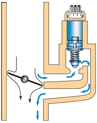
A by-pass valve opens or closes the air supply around the throttle valve so that the idle speed is stabilised. In the image below, a partially opened throttle valve can be seen on the left. On the right-hand side, an open by-pass valve allows air to be drawn into the engine through the by-pass channel. When the throttle valve opens further, the by-pass valve will close. After all, the by-pass is only needed when the throttle valve is closed. The engine management system determines how far the by-pass valve must be opened. The throttle position sensor, which indicates the opening angle of the throttle valve, provides the required information together with the intake air temperature sensor.
The by-pass that is often used is a pulse-width modulated spring-loaded solenoid valve. The engine management system supplies the solenoid coil with a PWM signal. By varying the duty cycle, the valve can be opened, closed, or set to any position in between. The by-pass valve can also be implemented with a stepper motor.
Pulse-width modulated by-pass solenoid valve:
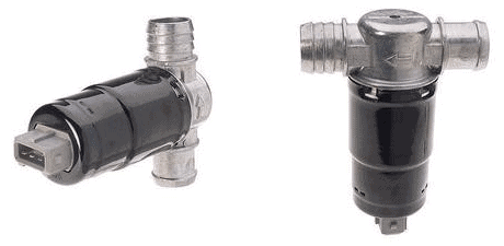
The image shows two views of a PWM-controlled by-pass valve. From the three pins on the connector it can be seen that this is often a version with two coils; one to open the valve and one to close it.
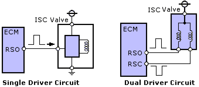
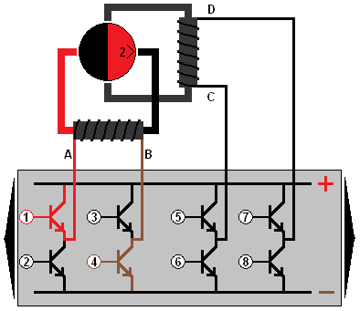
The diagram below shows how the two coils are controlled. When the “EFI Main Relay” (relay for the engine management computer) is switched on, the microprocessor is supplied with voltage. Two transistors are controlled in the ECU.
The switching method makes it possible for the lower transistor to invert the PWM signal of the upper one. The PWM signals are mirrored. This can be seen at ISC1 and ISC2 (the ECU outputs). The ECU varies the duty cycle for each coil. The difference in strength between the two magnetic fields determines the position of the valve. The frequency lies between 100 and 250 Hz.
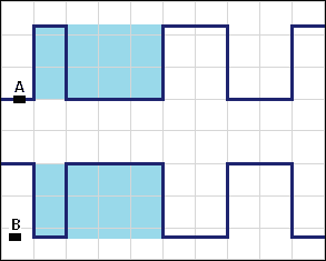
The duty cycle control can be measured with an oscilloscope. In the image below, the valve is half open (duty cycle 50%). On ISC1 and ISC2, the positive and negative pulses are equal.
Pulse-width modulated spring-loaded by-pass solenoid valve:
In addition to the actuator with two coils, this valve is also often implemented with a single coil. In that case there are usually two pins on the connector: one for the PWM control and one ground wire. A spring ensures that the valve is closed at rest; this makes the second coil unnecessary.
By-pass implemented with stepper motor:
In addition to the PWM-controlled by-pass valves, there are also valves that are adjusted by means of a stepper motor. The ECU controls the coils. Click here to go to the page about the stepper motor.
Throttle body with actuator motor:
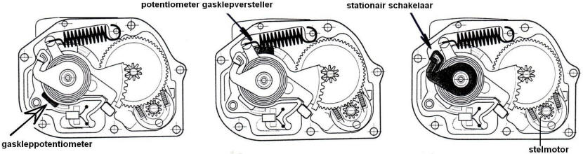
Modern engine management systems use throttle position control to stabilise the idle speed. A separate by-pass valve is therefore no longer necessary. All components for the throttle position control are located in the housing. Two potentiometers register the position of the throttle valve across the entire angle of rotation (in the middle of the image). Together with the idle switch, which detects idling (left), the signals are sent to the ECU. By means of a PWM signal, the DC motor in the throttle body is controlled to regulate the position of the throttle valve. Here too, a stepper motor may be used to rotate the throttle valve.
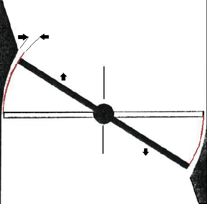
The inside of the throttle body housing is modified so that the air gap increases linearly with the angle of rotation of the throttle valve. This is very precise work. It is therefore important that the throttle position is reset in the basic settings with diagnostic equipment after replacing or cleaning the throttle body.
Throttle control in larger engines:
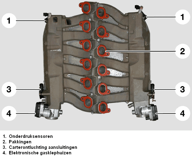
In large engines, such as the BMW V12 engine (shown in the image below), the air supply through a single throttle valve is insufficient. At full load the engine needs so much air that the diameter of a single throttle body would be too small. Therefore, two throttle bodies are fitted, one for each bank of cylinders. In this configuration there are two air filter housings, two mass air flow sensors and two intake pipes.
Throttle position sensor:
A throttle position sensor is located in a throttle body and passes the position of the throttle valve on to the ECU of the engine management system. The throttle position determines the amount of intake air, and therefore also the amount of fuel to be injected. Based on the throttle position, the ECU can adapt the idle speed control to the operating conditions: with a cold engine or with the air conditioning switched on, the idle speed needs to be raised slightly, so the throttle must open a bit more. See the paragraph: idle speed control.
In the following diagram we see an ECU and a potentiometer which are connected to each other with three wires. The potentiometer has a mechanical connection to the throttle valve. A rotation of the throttle valve will cause the wiper to move.
- On pin 3 the potentiometer receives a supply voltage of 5 volts;
- The potentiometer is connected to ground on pin 1;
- The signal from the potentiometer is sent to the ECU via pin 2: the wiper (the arrow) is connected to this wire.
The position of the wiper on the carbon track of the potentiometer determines the output voltage. When the wiper is positioned all the way to the left, the output voltage is high: the current only has to travel a short distance over the resistor, so less voltage is dropped. The further the wiper moves to the right, the lower the signal voltage will be. The page potentiometer explains the operation in more detail.
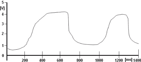
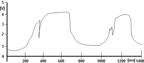
With a multimeter one can measure the supply voltage relative to ground. This must be a stabilised voltage of 5.0 volts. It is better to measure the signal voltage with an oscilloscope: noise can be present in the AM signal that is not visible with a multimeter measurement. The two drawings below show a correct signal (smooth lines) and a signal with interference, where the signal shows a strange voltage drop within a very short period of time.
In English-language, but sometimes also in Dutch-language literature, we often see the abbreviation “TPS” being used. This stands for “Throttle Position Sensor”, which is a translation of the Dutch “Gaskleppositiesensor” (throttle position sensor).
Electronic accelerator pedal (throttle by wire):
Nowadays the throttle valves are electronically controlled: we no longer find a (mechanical) cable between the accelerator pedal and the throttle valve. The position of the accelerator pedal is detected by two position sensors and sent to the ECU of the engine management system. The ECU checks whether the signals are plausible by comparing them with each other, and controls the throttle actuator (servo motor) to move the valve to a predetermined position. This is called “throttle by wire”, in Dutch: throttle control via wiring.
The accelerator pedal position sensors are mounted in the housing or on the top of the accelerator pedal. The signals from these sensors must be extremely accurate and reliable: under no circumstances do we want a fault in the signal to lead to unintentional acceleration or engine hesitation. To guarantee reliability, manufacturers use two position sensors:
- Manufacturers can choose to send the signals from both sensors at different voltage levels. When the signal voltage of sensor 1 rises from 1.2 to 1.6 volts, the signal voltage of sensor 2 will also increase by 400 mV, but then from 2.2 to 2.6 volts;
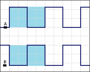
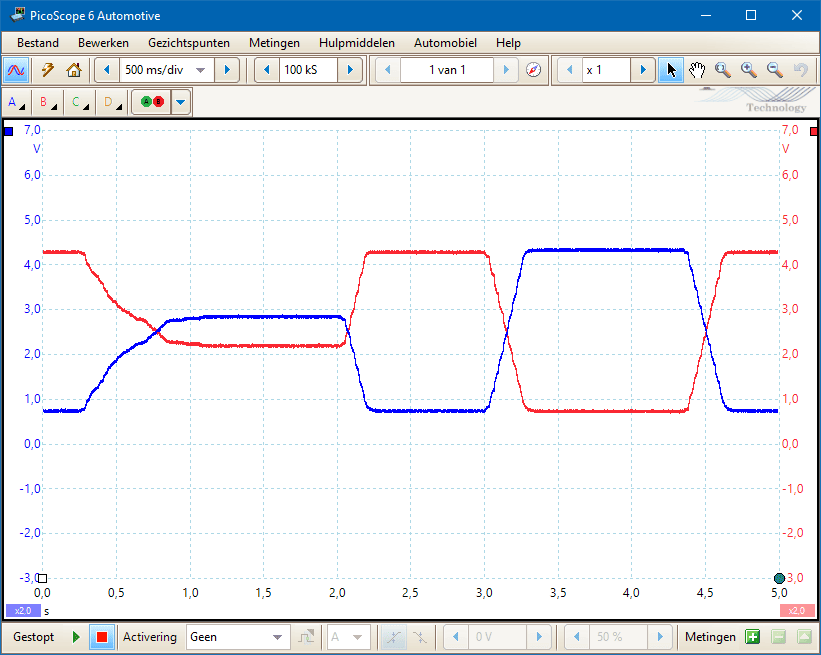
- Another option is to mirror two identical signals: The oscilloscope image below shows this strategy. When the accelerator pedal is actuated, the signal on channel A (blue) rises from 800 mV to 2.9 volts and the signal on channel B (red) falls from 4.3 to 2.2 volts. The amplitude (AM signal) of both signals is exactly the same, but mirrored.
When one of the two signals has a fault – the signal briefly drops to ground or shows noise – a difference will be seen between the two signals. The ECU can then decide to enter limp-home mode: the accelerator pedal position is no longer reliable. In limp-home mode only limited power is available, allowing the driver to reach a safe place at the roadside or possibly still drive to the workshop at a reduced speed.
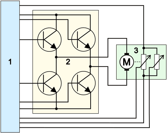
The throttle valve is opened and closed by a DC electric motor. The throttle actuator motor is controlled by an H-bridge. Like the accelerator pedal, the actuator motor is equipped with two potentiometers. The two images below show the throttle actuator motor (3) with two options for the dual potentiometers:
- Potentiometers with the wipers facing upwards: both signals have the same characteristic, but at a different voltage level;
- Potentiometers with the wipers opposed to each other: signals are mirrored. When opening the throttle valve one signal increases, while the other signal decreases.
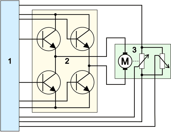
On the page H-bridge the control methods of the electric motor are described. On the page Potentiometer the operation and measurement of the position sensor are explained in detail.