Introduction:
Sensors measure physical quantities and convert them into electrical voltages. These voltages are processed in the microcontroller (ECU) and read as a “signal”. The signal can be evaluated based on the voltage level or the frequency with which a signal changes.
Passive sensors:
A passive sensor detects and measures a physical quantity and converts it into another physical quantity. An example of this is converting a temperature into a resistance value. A passive sensor does not generate its own voltage, but responds to a reference voltage from the ECU. A passive sensor does not require a supply voltage to function.
Passive sensors usually have two or three connections:
- reference or signal wire (blue);
- ground wire (brown);
- shielded wire (black).
Sometimes a passive sensor contains only one wire: in that case, the sensor housing serves as ground. A third wire can serve as shielding. The shield is grounded via the ECU. The shielded wire is mainly used for interference-sensitive signals such as those from the crankshaft position sensor and the knock sensor.
An example of a passive sensor is an NTC temperature sensor. The 5-volt reference voltage is used as a voltage divider between the resistor in the ECU and in the sensor, so not as a supply voltage for the sensor. The voltage level between the resistors (depending on the NTC resistance value) is read by the ECU and converted into a temperature. The circuit with the resistors is explained in the paragraph: “Power supply and signal processing” further on this page.
Active sensors:
Active sensors contain an electrical circuit in the housing to convert a physical quantity into a voltage value. The electrical circuit usually requires a stabilized supply voltage to operate.
This type of sensor in most cases has three connections:
- positive (usually 5.0 volts);
- ground;
- signal.
The stabilized 5-volt supply is provided by the control unit and used by the sensor to generate an analog signal (between 0 and 5 volts). The positive and ground wires from the ECU are often connected to multiple sensors. This can be recognized by junctions where more than two wires are connected.
The analog signal is converted into a digital signal in the ECU.
In the paragraph “power supply and signal processing” we will look at this in more detail.
Intelligent sensors:
Intelligent sensors are usually provided with three connections. As with active sensors, there is a power wire (12 volts from the ECU or directly via a fuse) and a ground wire (via the ECU or an external ground point). An intelligent sensor sends a digital (LIN bus) message to the ECU and the other sensors. In that case, there is a master-slave principle.
Internally in the sensor, an A/D converter converts an analog signal into a digital signal.
- Analog: 0 – 5 volts;
- Digital: 0 or 1.
In the LIN bus signal, a recessive state (12 volts) represents a 1, and a dominant state (0 volts) represents a 0.
Applications in automotive technology:
In automotive technology we can make the following classification of the different types of sensors:
Passive sensors:
- Knock sensor;
- Crankshaft position sensor;
- Temperature sensor (NTC / PTC);
- Lambda sensor (switching sensor / zirconium);
- Inductive height sensor;
- Switch (on / off)
Active sensors:
- Crankshaft / camshaft position sensor (Hall);
- Mass air flow sensor;
- Wideband lambda sensor;
- Pressure sensor (boost pressure / turbo pressure sensor);
- ABS sensor (Hall / MRE);
- Acceleration / deceleration sensor (YAW);
- Radar / LIDAR sensor;
- Ultrasonic sensor (PDC / alarm);
- Position sensor (throttle valve / EGR / heater flap).
Intelligent sensors:
- Rain / light sensor;
- Cameras;
- Pressure sensor;
- Steering angle sensor;
- Battery sensor
Measuring sensors:
When a sensor is not working properly, in most cases the driver will notice this because a warning light comes on or because something no longer functions correctly. If a sensor in the engine compartment causes a fault, this could lead to a loss of power and an illuminated MIL (Malfunction Indicator Lamp).
When reading out an ECU, a fault code can be displayed if the ECU detects the fault. However, not in all cases does the fault code lead directly to the cause. The fact that the sensor in question does not work may be because it is defective, but a problem in the wiring and/or connector connections cannot be ruled out.
It may also be the case that the sensor provides an incorrect value that is not recognized by the ECU. In that case, no fault code is stored, and the technician must use the live data (see the OBD page) to look for measured values that are out of range.
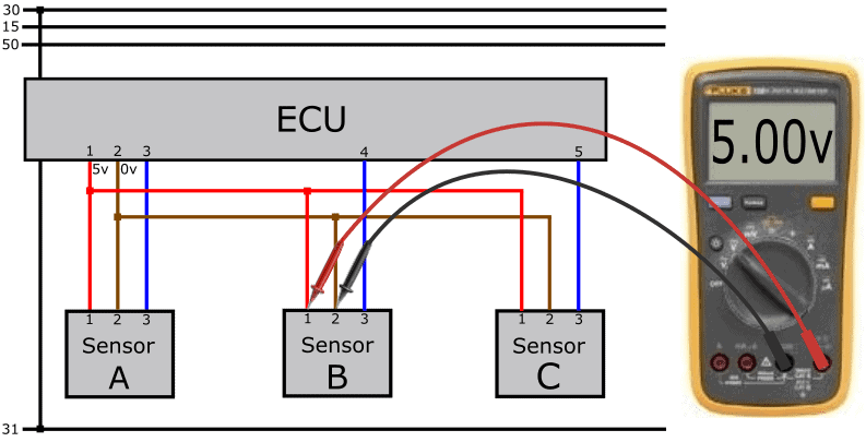
The following image shows a measurement of an active sensor. A digital multimeter is used to check the supply (the voltage difference at the positive and negative terminals) of the sensor. The meter indicates 5 volts, so this is in order.
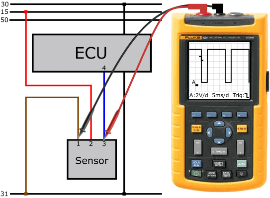
Signal voltages can be measured with a voltmeter or an oscilloscope. The type of signal determines which meter is suitable:
- voltmeter: analog signals that are virtually constant;
- oscilloscope: analog signals and digital signals (duty cycle / PWM).
With one or more measurements we can demonstrate that the sensor is not functioning properly (the emitted signal is implausible or the sensor provides no signal), or that there is a problem in the wiring.
For passive sensors, in most cases a resistance measurement can be carried out to check whether there is an internal defect in the sensor.
Possible problems in the sensor wiring can be:
- interruption in the positive, ground, or signal wire;
- short circuit between wires or to the bodywork;
- contact resistance in one or more wires;
- poor connector connections.
On the page: troubleshooting sensor wiring we look in depth at seven possible faults that can occur in sensor wiring.
Signal transmission from sensor to ECU:
There are different methods of transmitting signals from the sensor to the ECU. In automotive technology we may encounter the following signal types:
- Amplitude Modulation (AM); the voltage level provides the information;
- Frequency Modulation (FM); the frequency of the signal provides the information;
- Pulse Width Modulation (PWM); the time variation in the square wave voltage (duty cycle) provides the information.
The following three examples show oscilloscope signals of the different signal types.
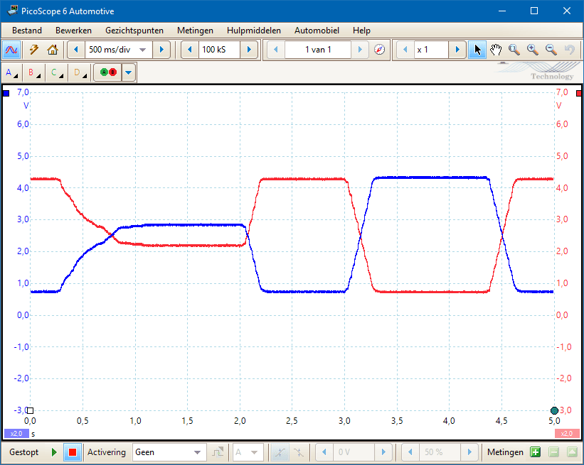
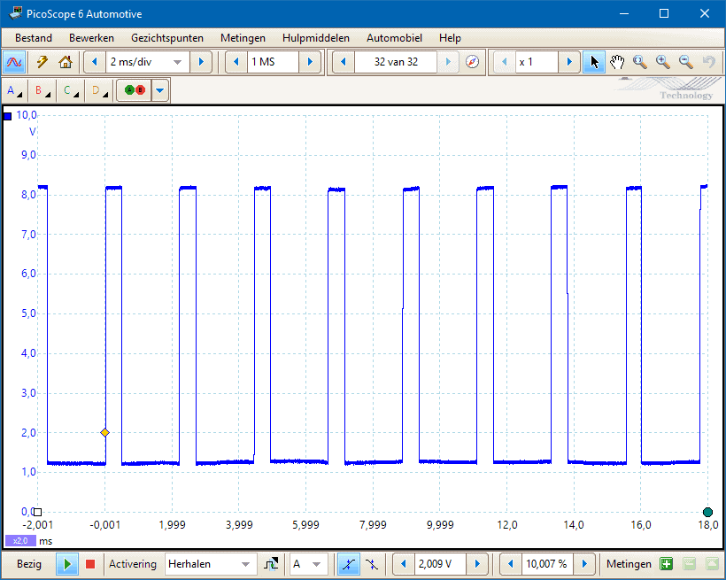
Amplitude Modulation:
With an AM signal, the voltage level carries the information. In the image, two voltages from the throttle position sensors can be seen. To guarantee reliability, the voltage curves must be mirrored relative to each other.
Voltages at rest:
- Blue: 700 mV;
- Red: 4.3 volts.
From approximately 0.25 seconds after starting the measurement, the accelerator pedal is slowly depressed and the throttle valve opens to 75%.
At 2.0 sec. the accelerator pedal is released and at 3.0 sec. full throttle is applied.
Voltages at full throttle:
- Blue: 4.3 volts;
- Red: 700 mV.
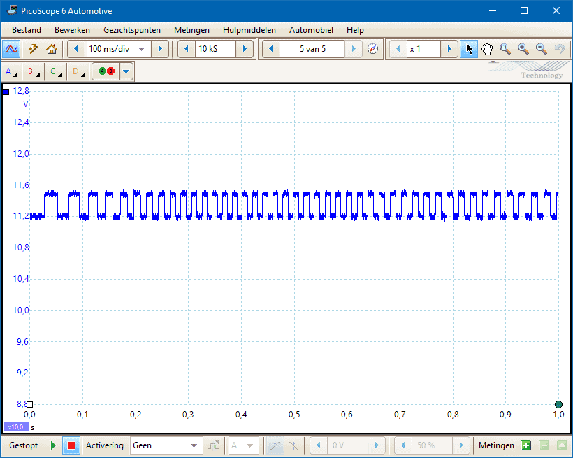
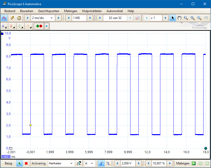
Frequency Modulation:
With sensors that transmit an FM signal, the amplitude (level) of the signal does not change. The width of the square wave voltage carries the information. The following image shows the signal from an ABS sensor (Hall). During the measurement, the wheel was rotated. At a higher rotational speed, the frequency of the signal increases.
The voltage difference is caused by changes in the magnetic field in the magnetic ring, which is integrated into the wheel bearing. The difference in level (low: magnetic field, high: no magnetic field) is only 300 mV. If the scope is set incorrectly (voltage range from 0 to 20 volts), the square-wave signal is barely visible. For that reason, the scale is adjusted so that the square-wave signal becomes visible, with the result that the signal is less clean.
Pulse Width Modulation:
With a PWM signal, the ratio between high and low voltage changes, but the period time remains the same. This should not be confused with a square-wave voltage in an FM signal: in that case the frequency changes and therefore the period time as well.
The following two images show PWM signals from a high-pressure sensor in an air conditioning line. This sensor measures the refrigerant medium pressure in the air conditioning system.
Situation during the measurement:
- Ignition switched on (sensor receives a supply voltage);
- Air conditioning switched off;
- Refrigerant pressure read with diagnostic equipment: 5 bar.
In the next oscilloscope image we see that the period time has remained the same, but the duty cycle has changed.
Situation during the measurement:
- Air conditioning switched on;
- High pressure has risen to 20 bar;
- Duty cycle is now 70%
Analog sensors can transmit a signal via AM. Such a voltage signal is sensitive to voltage loss. A contact resistance in a wire or connector results in voltage loss, and therefore also a lower signal voltage. The ECU receives the lower voltage and uses the signal for processing. This can cause malfunctions because multiple sensor values no longer correspond with each other, with the result:
- Two outside air temperature sensors that measure different temperatures at the same time. Although a small margin of error is acceptable and the ECU can take the average value, too great a difference can lead to a fault code. The ECU detects the deviation between the two temperature sensors.
- an incorrect injection duration because the signal from the MAP sensor is too low and the ECU thus interprets the engine load incorrectly. In that case the fuel injection is too long or too short, and the fuel trims will correct the mixture based on the lambda sensor signal.
In a PWM signal and/or SENT signal, voltage loss does not play a role. The ratio between rising and falling edges determines the signal. The voltage level does not matter. The duty cycle can be 40% at a voltage that fluctuates between 0 and 12 volts, but the ratio is still 40% if the supply voltage drops to 9 volts.
SENT (Single Edge Nibble Transmission)
The sensor signals mentioned above have been common in passenger cars and commercial vehicles for years. In newer models we increasingly see sensors that use the SENT protocol. In reality as well as in the wiring diagram, this sensor looks like a conventional active sensor.
With passive and active sensors, information is transmitted via two wires. In the case of a MAP sensor, for example: one between the NTC sensor and the ECU and the other between the pressure sensor and the ECU. The sensor electronics of a SENT sensor can combine the data transmission of multiple sensors, so the number of signal wires is reduced. In addition, the signal transmission is not affected by voltage loss on the signal wire, just like with a PWM signal.
A sensor that uses the SENT protocol has, just like an active sensor that sends an analog or digital signal, three wires:
- Supply voltage (often 5 volts)
- Signal
- Ground.
Sensors with the SENT protocol send a signal as an “output”. So there is no bidirectional communication, as is the case for example with LIN bus communication between sensors.
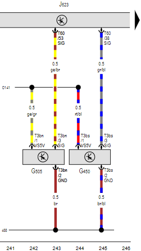
In the diagram on the right we see the differential pressure sensor (G505) of a VW Passat (model year 2022). In the diagram we see the usual designations of supply (5v), ground (GND) and signal (SIG). This pressure sensor converts the pressure into a digital SENT signal and sends it to pin 53 on connector T60 of the engine ECU.
In the example above, the differential pressure sensor sends only one signal using the SENT protocol over the signal wire. With SENT, multiple sensors can be connected to one signal wire. This can be applied, among other things, in a MAP sensor (air pressure and air temperature) and in an oil level and quality sensor.
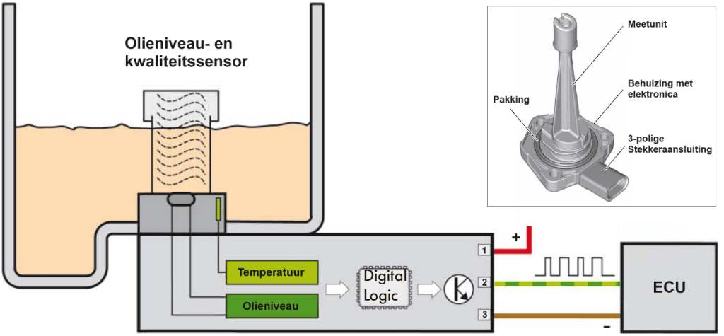
In the following image we see an oil level and quality sensor which is mounted in the oil pan of a combustion engine. Both measuring elements are located in the engine oil.
The sensor is supplied with 12 volts, receives its ground via the ECU and sends the signal to the ECU by means of SENT.
The microcontroller in the housing digitizes the message (see: “digital logic” in the image) in which both the oil temperature and oil level are included in the SENT signal.
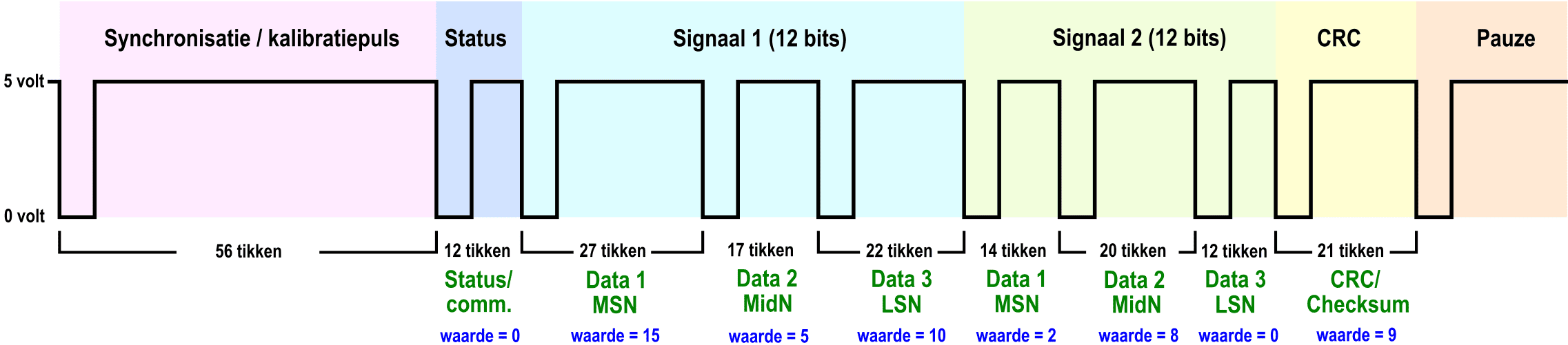
Below we look at the structure of a SENT signal.
A SENT signal consists of a sequence of nibbles (groups of four bits) that transfer information by sending voltages between 0 and 5 volts. Here is a brief description of how a SENT signal is structured. Below the image of the structure of the message is shown.
- Synchronization / calibration pulse: this is often the start of the message. With this pulse, the receiver can identify the beginning of the message and synchronize the clock timing;
- Status: this part indicates the condition of the transmitted information, for example whether the data is correct or if there are problems with it;
- Message Start Nibble (MSN): This is the first nibble and indicates the start of a SENT message. It contains information about the source of the message and the timing of the data transfer.
- Message Identifier Nibble (MidN): This nibble follows the MSN and contains information about the type of message, the status of the message and any error detection or error correction information.
- Data Nibbles: After the MidN one or more data blocks follow, each consisting of four data nibbles. These data blocks carry the actual data being transmitted. They contain information such as sensor data, status information or other useful data.
- Cyclic Redundancy Check (CRC): In some cases a CRC nibble can be added at the end of the message to facilitate error detection. The CRC nibble is used to check whether the received data has been correctly received.
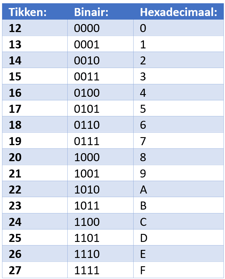
Each nibble in a SENT signal can have values from 0 to 15, depending on how many ticks it is at 5 volts. In the image below, the structure of the SENT protocol can be seen.
Groups of nibbles are transmitted, numerically from 0000 to 1111 in binary format. Each nibble represents a value from 0 to a maximum of 15, and they are displayed in binary as follows: 0000b to 1111b and in hexadecimal from 0 to F. These digitized nibbles contain the sensor values and are sent to the ECU.
To transmit this nibble information, so‑called “ticks” or computer ticks are used. The clock tick indicates how fast the data is transmitted. In most cases the clock tick is 3 microseconds (3μs) up to a maximum of 90μs.
In the first case this means that every 3 microseconds a new group of nibbles is transmitted.
The message starts with a synchronization/calibration pulse of 56 ticks. For each of the two signals, signal 1 and signal 2, three nibbles are transmitted, resulting in a series of 2 * 12 bits of information. After these signals the CRC
(Cyclic Redundancy Check) for verification follows, allowing the receiver to verify whether the received data is correct.
Finally, a pause pulse is added to clearly mark the end of the message for the receiver.
The oscilloscope images below (recorded with the PicoScope Automotive) show measurements of multiple messages (left) and a zoomed-in view of one message (right). In the zoomed-in message, the start and end of the signal are indicated in red. When the conditions change: the pressure and/or temperature rise, one or more nibbles will show a change in the number of ticks. The change in ticks will be visible in the oscilloscope image below as one or more voltages switching between 0 and 5 volts. The pulses can become wider or narrower. The actual information can be decoded with the PicoScope software.
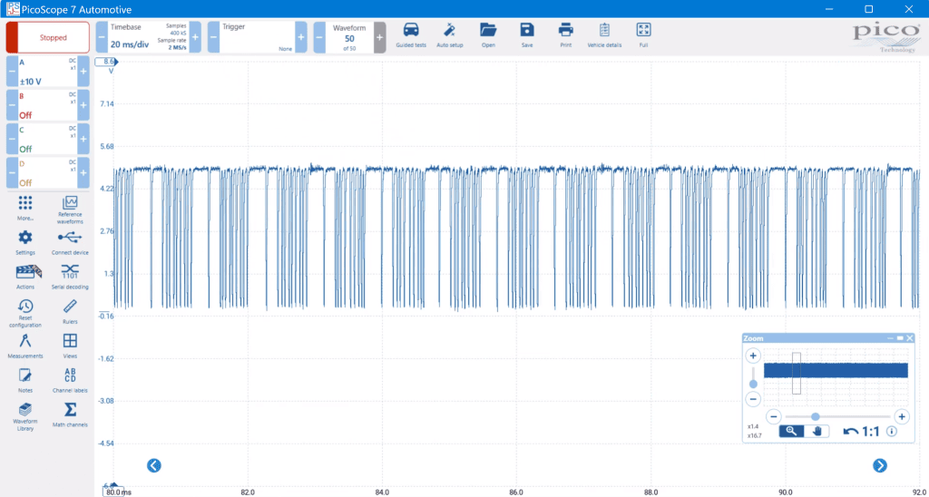
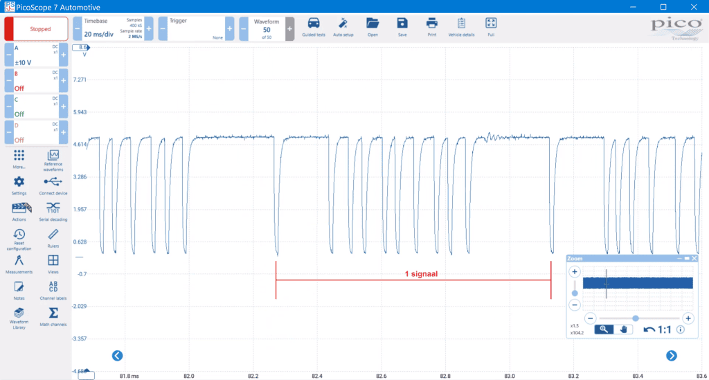
With an electrical diagnosis we can use the PicoScope software to decode the message for detailed analysis, but in most cases we focus on checking that the message pattern is clean and free from noise, and that the sensor’s supply voltage (5 volts) and ground are in order.
Power supply and signal processing:
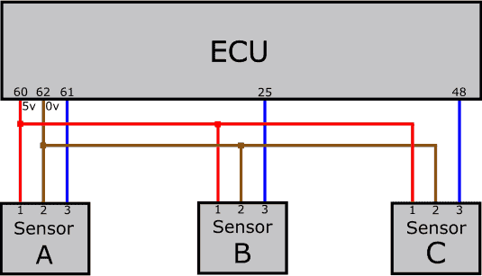
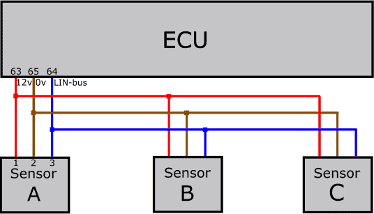
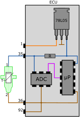
In the first paragraphs we discussed the presence or absence of a supply voltage. In this paragraph we discuss the main components in the ECU that are responsible for the power supply and signal processing of the sensor in question. The pin numbers in the detailed diagrams are the same as in the previous paragraphs: pins 35 and 36 of the ECU are connected to pins 1 and 2 of the passive sensor, etc.
In the first image we see an NTC temperature sensor. The reference voltage (Uref) from pin 35 of the ECU is obtained from the 78L05 voltage stabilizer. The voltage stabilizer supplies a voltage of 5 volts at a board voltage from 6 to 16 volts.
The resistor R (fixed resistance value) and RNTC (temperature-dependent resistance) together form a series circuit and also a voltage divider. The Analog-to-Digital Converter (ADC) measures the voltage between the two resistors (analog), converts it into a digital signal and sends it to the microprocessor (µP).
A multimeter can be used to measure the voltage at pin 35 of the ECU or pin 1 of the sensor.
On the page about the temperature sensor, in addition to some measurements with a good signal transmission, the measurement techniques in case of a wiring fault are shown.
In the second image the circuit of an active MAP sensor is shown.
The stabilized supply voltage of 5 volts reaches the so‑called “Wheatstone bridge“, which contains several fixed (R1, R2, R3) and one variable resistor (Rp).
The resistance value of Rp depends on the pressure in the intake manifold. Here, too, we are dealing with a voltage divider. The change in resistance causes voltage changes, so the bridge becomes unbalanced. The voltage difference that arises in the Wheatstone bridge is converted in the amplifier / filter into a voltage with a value between 0.5 and 4.5 volts. In the Analog-to-Digital Converter (ADC), the analog signal is digitized. The ADC sends the digital signal to the microprocessor.
The resolution of the ADC is in most cases 10 bits, divided into 1024 possible values. At a voltage of 5 volts, each step is approximately 5 mV.
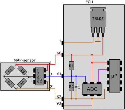
In the internal circuit of the ECU, one or more resistors are included in the power and signal circuits for both passive and active sensors. The resistor in the NTC circuit is also called the “bias resistor” and is used for the voltage divider. The resistors R1 and R2 in the ECU circuit of the MAP sensor are intended to allow a small current to flow from positive to ground.
Without these resistors, an open signal wire or disconnected sensor plug would cause a so‑called “floating measurement”. In such cases, the circuit with resistors ensures that the voltage at the ADC input is pulled up to about 5 volts (minus the voltage across resistor R1). The ADC converts the analog voltage into the digital value 255 (decimal), i.e. FF (hexadecimal), and sends this to the microprocessor.
Only a very small current flows through resistor R1 (low-ohmic). There is a small voltage drop of between 10 and 100 mV. It may occur that the applied voltage is a few tenths higher than 5 volts; between the ground terminal of the 78L05 voltage stabilizer and the ECU ground (brown wire in the diagram above) there is a low-ohmic resistor. The voltage drop across this small resistor can be e.g. 0.1 volts. The voltage stabilizer sees its ground terminal as the actual 0 volts, so it raises the output voltage (the red wire) by 0.1 volts. The voltage supplied to the positive terminal of the sensor is then not 5.0 but 5.1 volts.
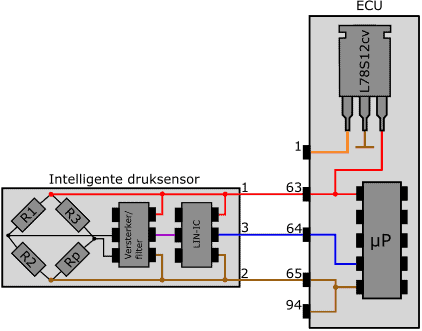
The intelligent sensor receives a voltage of 12 volts from the ECU. In the intelligent sensor, just like in the active sensor, a Wheatstone bridge and an amplifier / filter are incorporated. The analog voltage from the amplifier is sent to the LIN interface (LIN IC).
The LIN interface generates a digital LIN bus signal. The signal varies between 12 volts (recessive) and approximately 0 volts (dominant). With this LIN bus signal, the sensor communicates with the other slaves (usually the sensors and actuators) and the master (the control unit).
On the wire between pin 3 of the sensor and pin 64 of the ECU there are branches to the master and other slaves.
For more information, see the page LIN-bus.