Wheatstone bridge in balance:
The Wheatstone bridge is balanced or in equilibrium when the output voltage is equal to 0 volts, because the resistance values on the left and right are in proportion to each other.
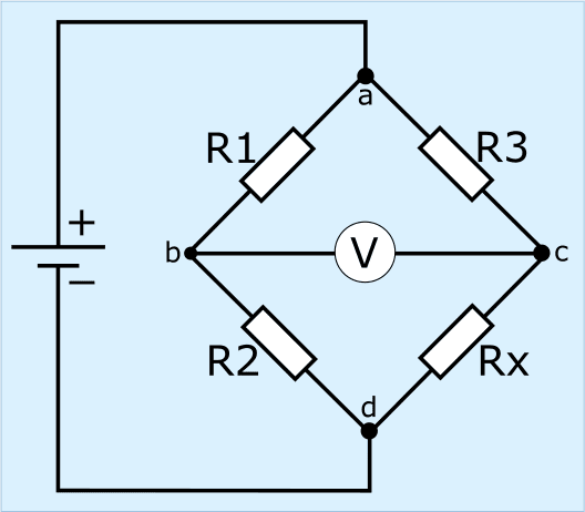
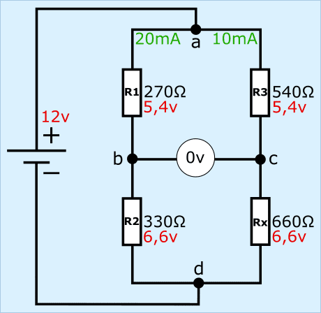
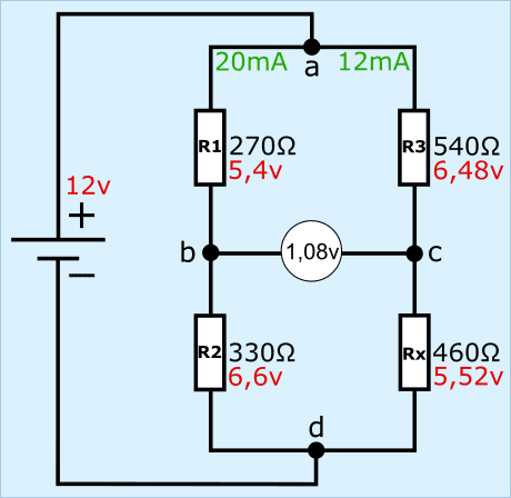
The circuit in this section is drawn differently than in the previous section, but is based on the same operation.
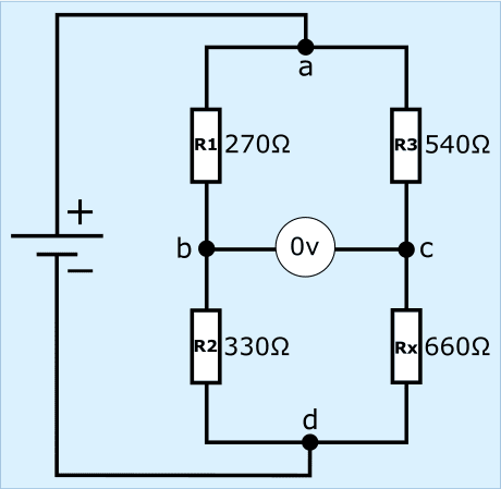
- the resistors R1 and R2 have a resistance of 270 and 330 Ω. Together this is 600 Ω;
- the resistors R3 and Rx have a resistance of 540 and 660 Ω. Together this is 1200 Ω.
The ratios between the resistances on the left and right are equal. This makes the resistance ratios and the voltage drops between R1 and R3, as well as R2 and Rx, equal.
The equal resistance ratios and voltage drops are shown in the formulas below:
![]() and
and ![]()
1. calculate the currents through resistors R1 and R2 (RV = equivalent resistance):
![]()
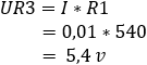
2. calculate the voltage drop across resistors R1 and R2:
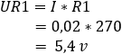
3. calculate the currents through resistors R1 and R2:![]()
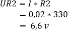
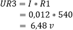
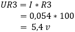
4. calculate the voltage drop across resistors R3 and Rx:
The voltage at points b and c is 5.4 volts. The potential difference is equal to 0 volts.
1. calculate the currents through resistors R1 and R2:
![]()
2. calculate the voltage drop across resistors R1 and R2:
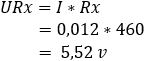
4. calculate the voltage drop across resistors R3 and Rx:
Method 1:
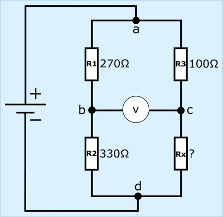
1. first we look at the general formula and then fill in the resistance values:
![]() –>
–> ![]()
2. between 270 and 100 there is a factor of 2.7, as there is between 330 and the unknown value.
By dividing 330 by 2.7 we arrive at a resistance of 122.2 Ω.
![]()
Method 2:
1. using the general formula in which we multiply the resistors crosswise:
![]()
2. we rearrange the formula by moving Rx to the left side of = and dividing by R1. This again results in the resistance value of 122.2 Ω.
![]()
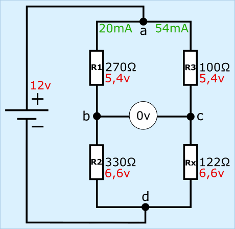
Of course we check whether we have a balanced bridge with the previously calculated resistance of 122 Ω.
The resistors R1 and R2 with the currents and partial voltages are the same as in the examples in sections 1 and 2, so they are considered known. We focus on the right-hand side of the bridge.
1. calculate the current through R3 and Rx:
![]()
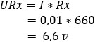
2. calculate the voltage drop across resistors R3 and Rx:
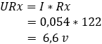
The voltage difference between points b and c is 0 volts because resistors R1 and R3 both take up 5.4 V, so the bridge is now in balance.