Introduction:
Every electrical consumer has an (internal) resistance. An electrical conductor, such as wiring, does have a low resistance value, but there is still specific resistance which depends on the material, dimensions and temperature. Every consumer also has a resistance value. The resistance value ultimately determines how much current flows through it.
Resistors can be found as components in almost all electronics. In automotive engineering as well, resistors are used in electrical circuits on, for example, circuit boards. A resistor limits the electric current through a circuit and converts the electrical energy into heat:
- increasing resistance: an ever smaller current flows through the circuit;
- decreasing resistance: the current becomes larger.
The resistor on a circuit board is connected in series with a component in which the current must not become too high.
The unit of resistance is ohm and is indicated by the Greek letter omega Ω. As the letter and symbol for resistance we use R (derived from the English term: Resistor).
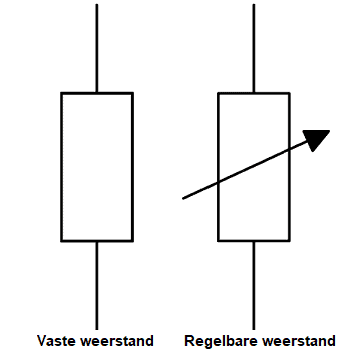
A resistor can be made as a fixed resistor or as an adjustable resistor. The image beside this text shows the symbols of these two types of resistors. The symbol consists of a rectangle with a line on each side. Often the letter R with the resistance value in ohms is shown in or next to the rectangle in a diagram.
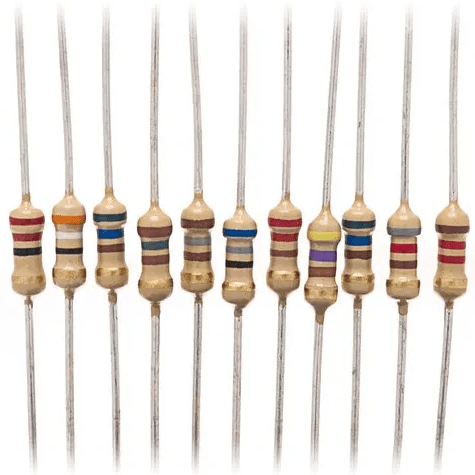
- Resistors with a fixed resistance value are often recognizable by the colored rings around the housing. The resistance value can be determined from these colored rings;
- Resistors with a variable value are usually adjustable with a rotary knob. This type of resistor can also be made as a potentiometer, which is often used as a position sensor.
The following paragraph shows the different types of resistors that we may encounter in the automotive field.
Types of resistors:
The image below shows an overview with twelve different types of resistors. Below the image, the construction and application of each type of resistor are described per category.
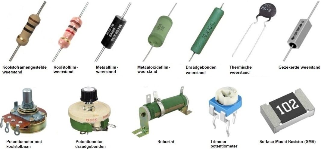
The resistors commonly used in the automotive field and in practicals for automotive courses are shown below. For each resistor, the construction is described based on the materials from which the resistors are made.
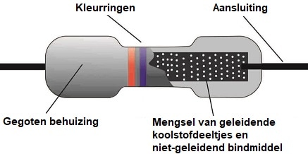
Carbon composition resistor:
This resistor has a cylindrical shape and contains colored rings with which the resistance value can be looked up. The resistive element consists of carbon powder or graphite powder, mixed with ceramic clay. The resistor is covered with a molded plastic housing. These resistors are known for a poor temperature coefficient and low reliability in terms of noise and accuracy. This type of resistor has been replaced by the film type.
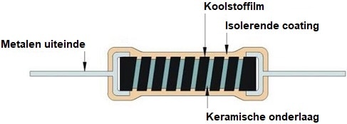
Carbon film resistors:
The carbon film resistor consists of a ceramic substrate with a thin layer of carbon film over it. The resistance value is determined by the groove.
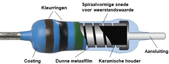
Metal film resistor:
The metal film resistor is very similar in construction to the carbon film resistor. With this type of resistor, however, a metal film is applied to a ceramic layer.
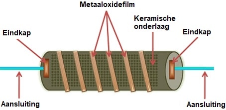
Metal oxide film resistor:
The construction of this resistor has many similarities with a metal film and carbon film resistor. Instead of metal or carbon, a metal oxide film is deposited on the ceramic substrate.
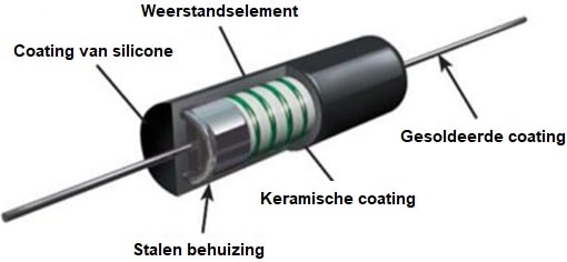
Wire-wound resistor:
The wire-wound resistor contains a metal resistance wire which is wound around ceramic material. The resistance depends on the thickness of the metal wire. The accuracy of the wire-wound resistor is high. Due to the resistance wire, the temperature coefficient of resistance is so low that this resistor is very suitable for applications where a high power is required.
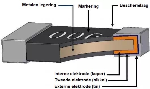
SMD resistor:
The SMD resistor is often called a “chip resistor” and consists of a metal alloy (made of metal oxide or a metal film) with a three-layer electrode structure on both sides. The length, thickness and material used determine the resistance value. The inner electrode is connected to the metal alloy. The middle electrode is made of nickel and its function is to guarantee heat resistance during soldering. The outer electrode is a tin layer and makes the resistor suitable for being soldered directly onto the PCB.
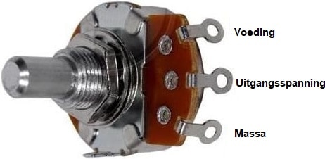
Potentiometer:
The potentiometer behaves as a variable resistor. The resistance value depends on the position of the slider on the carbon track. When a supply (often 5 volts) and ground are connected, the output voltage is between 0.5 and 4.5 volts, depending on the position of the rotary knob.
More information can be found on the page: Potentiometer.
Properties of resistors:
When we want to use resistors, we have to choose the type of resistor that is suitable for the required properties: is high accuracy at low power needed, or is high power needed where noise in the system is not important?
- Maximum voltage: the maximum voltage rating of a resistor must not be exceeded. If it is exceeded, breakdown can occur. This can affect the resistance value;
- Maximum power: if the power rating of the resistor is exceeded, the temperature will rise too high. The resistance value can change. The power ratings of carbon resistors are often 0.25 watt to 1 watt and of wirewound resistors 3 watt to 20 watt.
- Tolerance: a resistor never has exactly the value that is printed on the housing. A percentage is printed on the housing indicating the deviation. This deviation in percent is caused by the precision of the production process. A resistor of 120 ohms with a tolerance of 5% can be at least 114 ohms and at most 126 ohms.
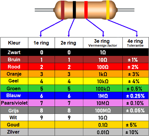
Color coding:
The value and tolerance of a resistor is indicated on a carbon or wirewound resistor by means of a color code (color bands) on the resistor body. It is important to start reading from the correct side:
- the first band is often closer to the end of the body;
- the first band is often wider;
- the last bands may be silver or gold. These colors are not used for the first bands.
When a resistor has four bands, the meaning of the bands is as follows:
- Band 1 and 2: resistance value;
- Band 3: multiplication factor;
- Band 4: tolerance.
In the image we see a resistor with the 1st band brown, 2nd band black, 3rd band red and the fourth band gold. In the table we read the numbers: 10*100 ± 5%. The resistance value is 1000 Ω (1 kΩ) with a tolerance of 5%. The actual value lies between 950 and 1050 Ω.
Resistors are found in series. We often encounter the E12 series, in which the resistance values increase as follows:
10, 12, 15, 18, 22, 27, 33, 39, 47, 56, 68, 82.
These values can be divided or multiplied by ten, for example 100, 120, 150, 180. Or, 1000, 1200, 1500, 1800. Resistors of 130 ohms do not exist.