Introduction:
Modern vehicles are equipped with a lot of electronics. They often contain dozens of ECUs, each of which is responsible for specific functions.
- Engine compartment: ECU for engine electronics, automatic transmission, ABS/ESP;
- Interior: ECU for the airbags, in the doors, under the seats, in the roof for the sunroof or lighting, in the luggage compartment for the tow bar electronics, etc.
These ECUs and actuators receive their power directly from the fuse box. Because there are multiple power wires and fuses, we can often find several fuse boxes, such as in the engine compartment, the dashboard and even in the luggage compartment of passenger cars.
From the fuse box, power wires (positive) run to various components, such as ECUs and actuators. The ECUs receive information from sensors via signal wires.
An example in the interior is the door switch, which indicates 12 or 0 volts respectively when open or closed. In the engine compartment, the coolant temperature sensor can send a signal of 2.5 volts to the ECU at a temperature of 20 degrees Celsius and a signal of 0.5 volts at 90 degrees Celsius.
The ECU then controls the actuator, supplying current to a passive actuator (e.g. an injector), sending a voltage signal to an active actuator (COP coil), or sending a digital message to an intelligent actuator (windscreen wiper motor). Each ECU and actuator is connected via one or more ground wires to a ground point on the body or chassis of the vehicle.
All positive, ground, signal and communication wires between the fuse boxes, ECUs, sensors, actuators and ground points add up to an enormous amount of wiring. Manufacturers route wiring through the vehicle as much as possible in a single bundle. We call this a wiring harness.
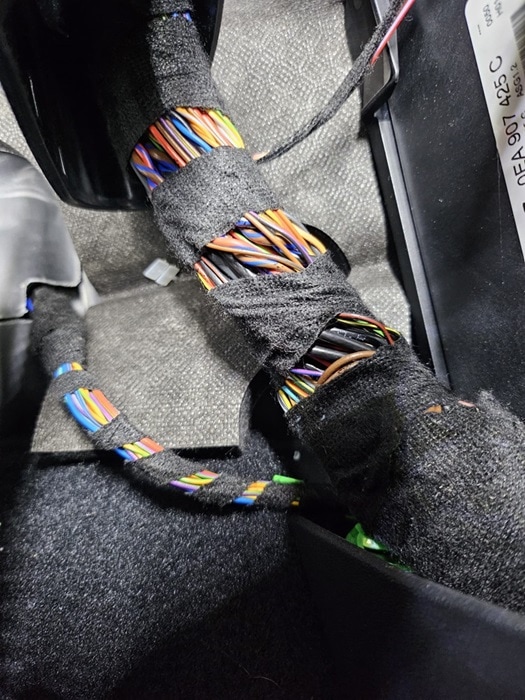
In the following image we see part of the wiring harness through which dozens of wires run. The wiring harness is wrapped with tape to keep the wiring together. The colours are still visible between the windings of the tape, so that a technician can easily identify the wire colour when troubleshooting.
A wiring harness has many branches: the harness runs from the engine compartment to the luggage compartment, but also from the left to the right doors, under the dashboard from left to right and under the seats. The wiring harness is made to fit the vehicle exactly.
A wire in a wiring harness can become damaged. If the insulation has frequently been damaged by repeated bending (for example at the hinge of a door or tailgate), or if the wire has chafed against something, the wire can in most cases be repaired. The damaged section is removed and a new piece of wire is soldered in between and then sealed with heat-shrink tubing. However, when there is a short circuit and burned-through wires, it becomes more complicated. In that case, especially for a car with a high current market value, it may be decided to install a new wiring harness.
Wire thicknesses:
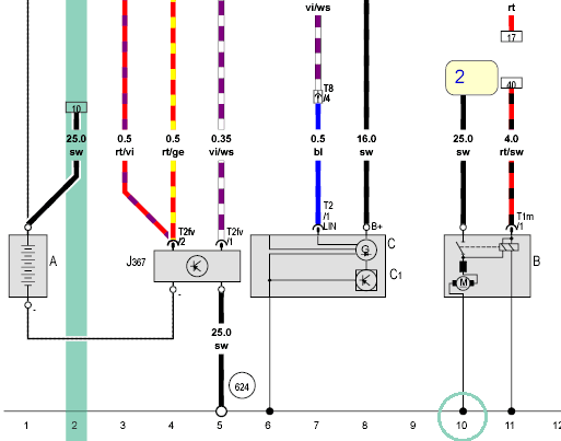
In the car we find many different wire thicknesses. In the engine compartment we find thin wires for sensors and relatively thick wires to actuators. In the following diagram we see a black (ground) wire on the battery (A) of 25.0 mm². This is the thickest wire we find in the engine compartment. On the alternator (C) we see on the B+ a black wire of 16.0 mm². On the control unit J367 we find much thinner wires of 0.35 to 0.5 mm².
The choice of wire thickness has to do with the maximum current and the length of the wire in relation to the specific resistance of the wire:
- A thick wire is suitable for higher currents;
- The longer the wire, the higher the resistance of the wire becomes. Long wires are therefore often made thicker.
A negative and B+ cable from the alternator must conduct a high current. A thin wire would have too high an internal resistance, which would not only cause a voltage drop, but also an increase in temperature. Only a small current flows through the wires to the ECU.
The resistance in the wire has a major effect on the voltage drop. The current plays a major role in this. To make this clear, two calculations follow below. In both examples, the resistance of the wire is 0.1 Ω.
We take a positive wire of a 21 Watt lamp and calculate the current by dividing the power by the supply voltage of 12 volts (the power law). The current is, depending on the temperature, around 1.75 A. Using Ohm’s Law we calculate the voltage drop over a wire.
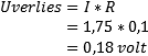
The voltage drop of 0.18 volts is acceptable, since the lamp burns at a voltage of (12 – 0.18) 11.82 volts. For clarity: the 0.18 is V3 in the V4 measurement. The resistance in this wire is therefore low enough not to have a negative effect on the operation of the consumer.
In the next example we take the positive wire of the starter motor. Again, the resistance of the positive wire is 0.1 Ω. The measured starting current is 90 amperes.
The resistance in the wire causes a voltage drop of 9 volts. With a voltage of 12 volts with the starter motor engaged, only 3 volts remain to operate the starter motor. This is of course far too little; the starter motor will hardly start to turn, if at all.
Conclusion: a resistance of 0.1 Ω in a positive wire has hardly any consequences for a lamp, but is so high for a starter motor that it will no longer function.
Specific resistance of the wire:
Every wire has an ohmic resistance. The resistance value depends on:
- the material;
- the dimensions (length and diameter);
- temperature.
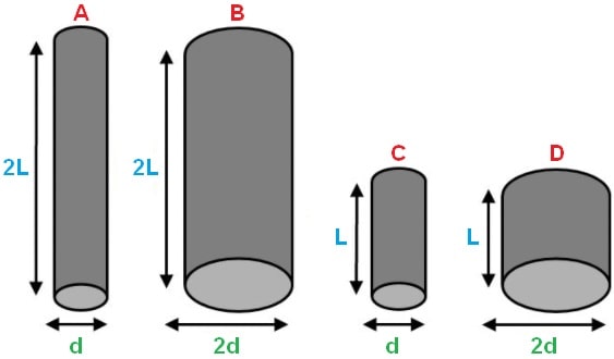
The following image shows four wires of the same material, of which wire A has the highest and wire D the lowest resistance.
- In proportion, 2L is twice as long as l;
- In proportion, 2d is twice as long as d.
A thick, short wire has less resistance than a thin, long wire.
The resistance of a wire can be calculated with the following formula:
In this formula:
- R is the resistance of the wire in ohms [Ω];
- l is the length of the wire in metres [m]
- ρ (rho) is the specific resistance of the wire in ohm metre [Ωm]
- A is the cross-sectional area of the wire in square metres [m²]
The formula shows that the resistance of the wire increases with a greater length (l), and decreases with a larger cross-section (A). We express the specific resistance of a wire in ohm metre (Ωm). Because we are dealing with small numerical values, we use a unit that is 10^6 times smaller, namely micro-ohm metre (μΩm).
Example:
We calculate the resistance of a copper wire with a length of 2 metres and a cross-section of 1.25 mm² and a specific resistance of 0.0175 * 10^-6 Ωm.
Connector connections:
In the car, wires are connected to a sensor, actuator or control unit by means of a connector. It is also possible that there is a connector somewhere in a wiring harness that allows two wiring harnesses to be connected to each other.
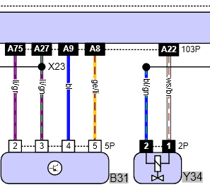
The following image shows part of a diagram of a Ford Fiesta. Here we see the component code B31 (mass air flow sensor) and Y34 (charcoal canister solenoid valve). The mass air flow sensor is a sensor and the solenoid valve is an actuator. They are both connected to the engine control unit (at the top).
On the mass air flow sensor we see a 5-pin connector (5p) with four occupied positions: 2 to 5.
The solenoid valve is equipped with a two-pin connector (2P).
The numbers on the connector in the diagram are in reality shown on the connector itself. In this way, the wire colours can be compared, or, when the same wire colour is used in several positions, the wire functions can be distinguished from each other (positive, ground, signal, etc.).
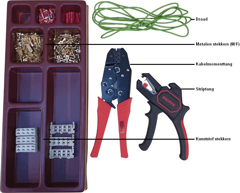
Wire repair:
During a wire repair it may be necessary to crimp a new connector onto the wire. We do this with a cable crimping tool, also called a crimping tool. In this example, uninsulated metal terminals are crimped onto the wire and clicked into plastic connector housings.
In the cable crimping tool there is a mechanism by which a large torque can be applied to the cable shoe or metal terminal with a minimum force on the handle. Usually there is also a holding mechanism, so that the tool “clicks” into place while squeezing and holds the cable shoe when the handle is released. Only when the tool has been fully squeezed into its end position, or when the release mechanism is operated, does the tool release the cable shoe again.
Determine the length of the wire and cut off a section. Keep in mind that a section of insulation will still be removed from the ends with the wire stripper.
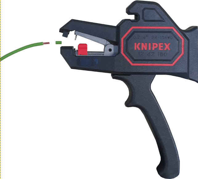
The two images below show the wire stripper and the end of the green wire:
- left: first determine the length to which you want to strip the wire by setting the red part to a different position. All the way to the left, as in the image, the length is 2 mm. Squeeze the tool. The jaws close and the metal mechanism grips the insulation. Squeeze the tool all the way. The insulation is slid off the wire at the preset distance;
- right: release the tool. The copper wire is now visible.

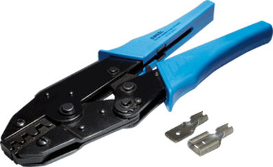
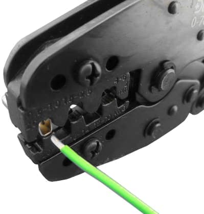
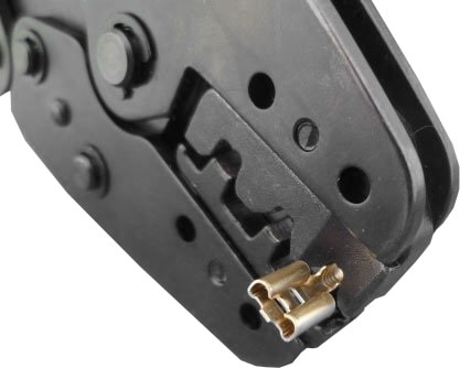
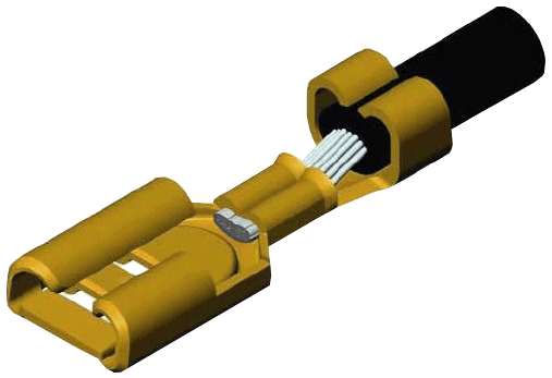
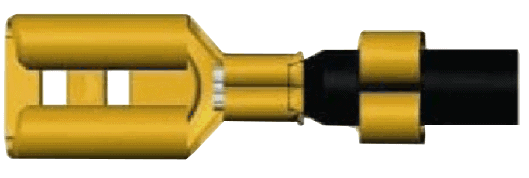
After the wire has been stripped (the copper wire is 2 mm long) cable terminals (insulated / uninsulated) or metal terminals can be crimped onto it. The three images below show the following:
- Left: a cable crimping tool with two metal terminals (male and female);
- Middle: the metal terminal is clicked into the cable crimping tool and the stripped wire is inserted into the rear of the metal terminal;
- Right: the other side of the cable crimping tool with the metal terminal.
Correct (1)
Mistakes are sometimes made when crimping cable terminals. It is important to know how far to strip the electrical cable and how far the wire must be inserted into the terminal. Below are five examples including the three most common mistakes.
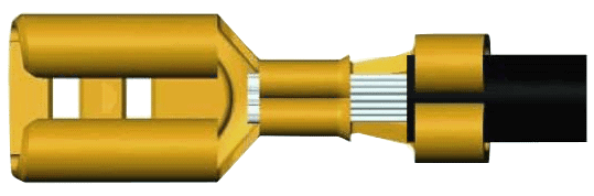
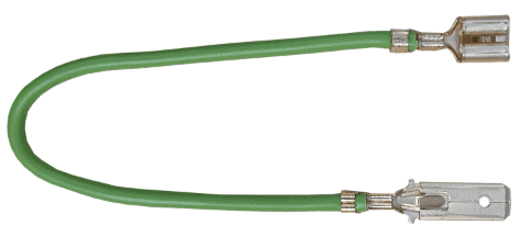
In the following image a properly mounted wire can be seen.
Correct (2)
This is the same wire, drawn from a different angle.
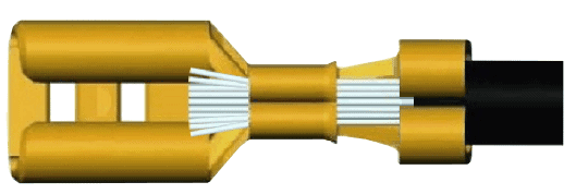
Incorrect (1)
The insulation has been stripped far too much. The copper wire protrudes and, in some connector housings, after bending the ends, can cause a short circuit.
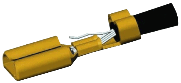
Incorrect (2)
Not all of the copper wire has been crimped into the terminal. The protruding strand can, when bent, cause a short circuit with another wire in the connector, or against the vehicle body.
Error 3:
The insulation has been stripped too short and has been crimped in the inner part of the cable lug. Because this part is thicker than the copper wire, the cable lug has not been fully crimped closed. The possible result is poor contact between the copper wire and the cable lug.
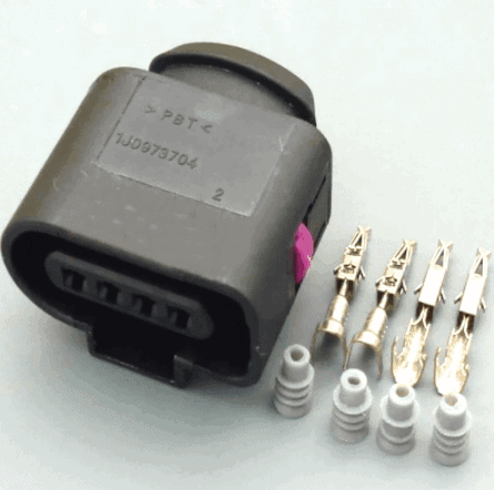
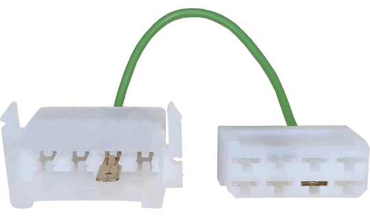
After crimping the two metal terminals onto the wire, they can be clicked into the plastic connector housings.
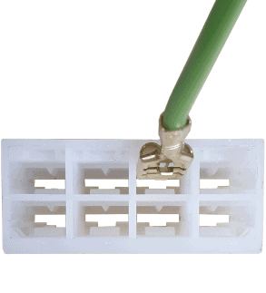
It may happen that the wire has accidentally been clicked into the wrong position. Using a lampholder screwdriver or a terminal extractor, the barb on the terminal can be carefully bent and the wire pulled out of the connector. Of course, the barb must then be bent back up again, otherwise the terminal will no longer latch in place.
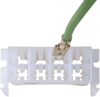
Unlocking connectors:
It may be necessary to remove a wire from a connector. The metal connector that is crimped onto the end of the wire must therefore be removed from the plastic connector housing. For this, a tool is required: a so-called terminal extractor. With this, the barbs on the metal connector in the plug can be bent so that the wire can be pulled out of the connector. To be able to do this, the lock in the connector must first be removed; in the image, the lock can be recognized by the purple plastic part halfway along the connector. The lock prevents the wire from being pulled out of the connector, even when the connector has been unlocked with the tool. The animation shows the unlocking and removal of the wire from a four-pin connector used in an Audi.