Introduction:
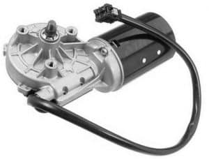
The rear wiper motor is mounted in the tailgate of the car. There is a hole in the window or in the bodywork of the tailgate through which the shaft of the wiper motor protrudes. The wiper arm with the wiper blade is mounted on this shaft. The shaft obviously cannot make full rotations, because in that case not only the rear window but also the rest of the tailgate or rear bumper would be wiped clean by the wiper blade. That is why there is a small mechanism in the motor that ensures that the shaft can move a maximum of 180 degrees.
The rear wiper motor always has one speed. With the wiper switch it can be switched on and off, and it usually has an intermittent mode; after switching on, the motor will be activated every few seconds.
The wiper always returns to the initial position after it is switched off. If that did not happen, the wiper arm would stop halfway up the window when the switch is set to the “off” position. Instead of the supply voltage to the motor being cut off, it remains present until the zero position is reached.
Components of the wiper motor:
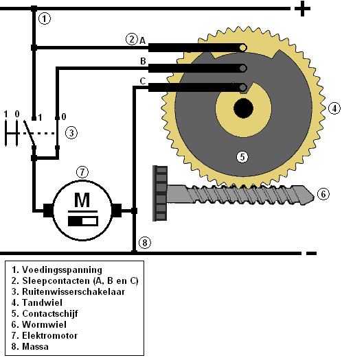
To move the wiper arm back to the starting position, it contains an internal contact plate with sliding contacts. The following images are used to explain how the wiper motor works.
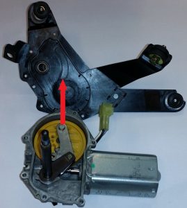
The back plate of the wiper motor has been removed here. The red arrow indicates where the round pin of the mechanism in the back plate moves back and forth. The mechanism ensures that the rotating movement of the yellow plastic gear is converted into a reciprocating movement of the output shaft. The output shaft is shown upright in the image. The wiper arm is mounted on this shaft.
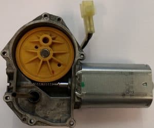
The image on the right shows the cutaway wiper motor with the worm gear and plastic gear. Here the mechanism has been removed.
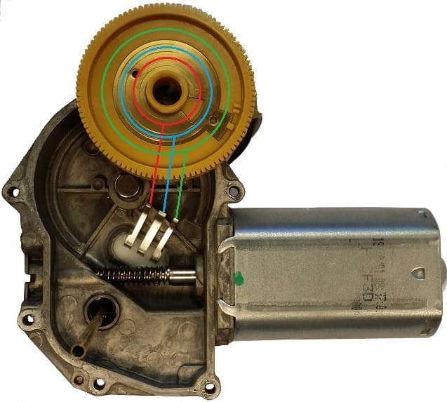
The following text refers to the image below. The yellow plastic gear has now been turned over. Here the notches and recesses of the conductive contact disc are clearly visible. Red, blue and green indicate the positions where the sliding contacts touch the contact disc.
To show at which positions the sliding contacts make contact with the conductive contact plate, they are marked in red, blue and green. Below is what the sliding contacts are for:
Red: This always has 12 volts when the ignition is on.
Blue: This sliding contact is responsible for the zero position.
Green: This is the ground. With this, the motor is connected in the zero position.
The three sliding contacts “slide” over the gold-coloured contact plate when the motor is running. A notch and a recess have been made in the contact plate. The sliding contacts therefore never touch the contact disc all three at the same time. The middle one (marked in blue) is responsible for the movement to the zero position. The contact plate is conductive; if the motor is not yet in the initial position, the inner (red) and middle (blue) sliding contacts are connected to each other. The voltage is transferred via the contact plate from the red to the blue contact. As a result, the motor can keep running until the red sliding contact reaches the notch. At that moment it can no longer pass voltage on to the blue contact. The control of the motor is then stopped.
At that same moment, the outer sliding contact, via the recess (marked in green), makes contact with the blue sliding contact through the contact plate. The green sliding contact is connected to the vehicle ground. This sliding contact acts as a kind of brake. This brings the wiper motor to a stop. The ground is passed from green to blue. The motor is short-circuited to ground on both sides and therefore remains in the zero position.
Connecting the wiper motor:
To connect the wiring of the wiper motor, the operation of, among other things, the contact plate and the sliding contacts must first be studied. Only when one understands at which points voltages will be present, can one proceed to measuring and connecting the wiring.
The wiring harness in the tailgate for the rear wiper motor often consists of three or four wires. A constant voltage, switched voltage and a ground must be measured on these wires. On the remaining wire on which nothing is measured, a supply voltage (with a ground-switched motor) or a positive (with a positive-switched motor) will often be present when the motor is in the rest position. A measurement on this wire can therefore only be carried out when all wires are connected and the wiper motor is in the initial position. In all other cases nothing will be measured.
There are positive-switched and ground-switched wiper motors. This means that the switch is located on the positive or on the ground side of the electric motor. It is very important to know this before starting to measure. In the chapters below, each step is described in detail. Pay close attention to the differences between the positive-switched and ground-switched variants!
Wiper motor with switched positive:
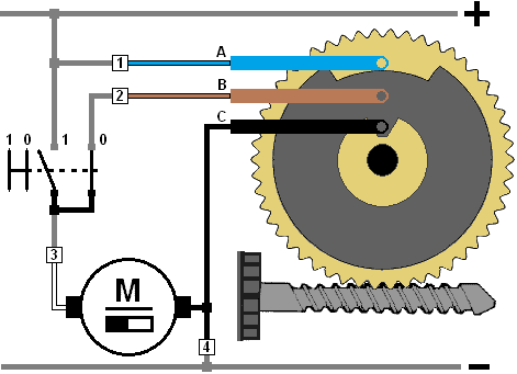
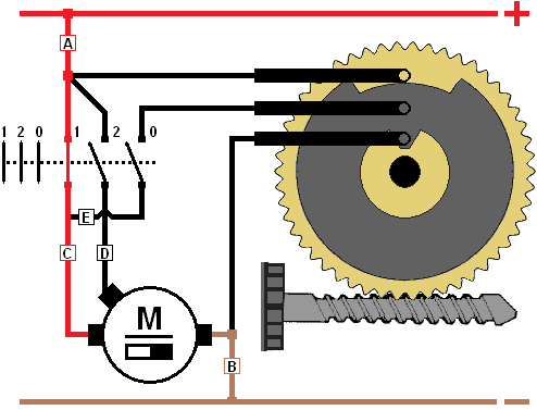
Using the diagrams, you can also see how this should be connected for, for example, the notorious part of the practical exam. Below is a diagram with a legend of the rear wiper motor with switched positive. The wiper motor is stationary and switch “0” is closed.
The electric motor (7) only receives direct battery voltage at a constant speed. In that case, switch 1 is closed and switch 0 is open. The electric motor (7) drives the worm gear (6), which in turn rotates the gear (4). The grey conductive contact disc is attached to the plastic gear and will therefore also rotate. When the wiper switch is set to the off position, the contact disc (5) and sliding contacts A, B and C (2) ensure that the motor stops in the correct position. This is clarified below.
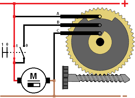
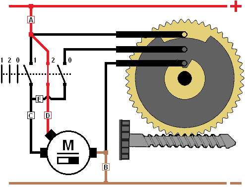
Wiper motor switched on:
In this situation, the wiper motor is switched on. The supply voltage is provided via the red positive wire. Switch 1 is closed, so the motor receives a constant supply voltage. The other side of the motor is connected to ground, so the motor will run at a constant speed. The worm gear is driven by the wiper motor and will therefore also rotate. In this case, that has no effect on the power supply to the motor.
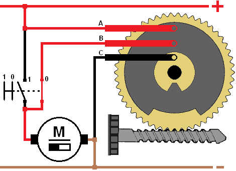
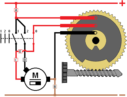
Switch in off position, wiper still moving:
In the image below, the wiper switch has been set to the “off” position. This opens switch 1 and closes switch 0 (for the zero position). At this moment, current flows via sliding contact A, via the grey contact plate to sliding contact B. The current then flows from sliding contact B, via switch 0 to the wiper motor. Because the gear is driven by the wiper motor via the worm gear, the contact plate will also rotate. The motor will continue to run until the notches of the contact plate are at the top again.
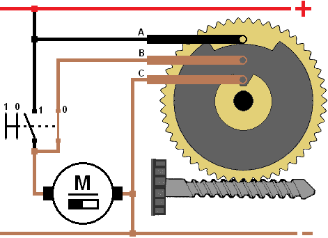
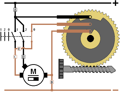
Switch in off position; wiper stops:
The gear continues to turn until the notches of the contact plate are at the top. This interrupts the contact between sliding contacts A and B. Sliding contact A is insulated by the (yellow) plastic gear, so no current can flow to sliding contact B. No current will then flow to the wiper motor either. When the contact plate has rotated far enough, sliding contact C also makes contact with the small conductive part of the contact plate. At this moment, sliding contacts B and C are connected to each other. Because C is always connected to ground, B now also makes contact with ground via the contact plate. At this point, the wiper motor is connected to ground on both sides, so that it stops immediately. This in fact acts as a kind of brake. This way, the wiper motor always stops in the same position.
Animation:
In this animation, the different positions of the switch and the contact plate can clearly be seen. Here is a brief summary of the explanation given above.
- Switched off: the switch is in the zero position and the electric motor is short-circuited with positive and ground.
- Switched on, constant speed: the switch is in position 1 and the contact plate makes two revolutions clockwise. In this position the contact plate is not used.
- Switch position 0, rotating to zero position: the contact disc provides the power supply to the motor until the notches have reached the sliding contacts.
- A-B (positive interrupted), B-C make contact. This has a braking effect on the motor, which then comes to an almost immediate standstill.

When, for example, during a practical exam, wiring has to be connected, the correct positions of the switch must be found. With the wiper motor diagram, it can be read which pin in the connector is responsible for the power supply, ground or zero position. By measuring which wire in the car’s wiring harness has 12 Volts, that one can already be connected. Using a resistance measurement, it can be determined which connection is the ground. The ohmmeter will show a resistance value of less than 1 Ohm at this connection. The negative lead must, of course, be held on a good grounding point on the bodywork. By then moving the switch through several positions, you can find out which wire belongs to which switch position. Then, using the diagram, you can determine which wires must be connected to each other.
From theory to the manufacturer’s diagram:
The theory of the rear wiper motor was discussed in the previous paragraph. In the diagrams it can clearly be determined how the contact plate in the cutaway wiper motor ensures that the motor receives power to rotate back to the initial position. This paragraph explains how this diagram can be translated into a manufacturer’s diagram.
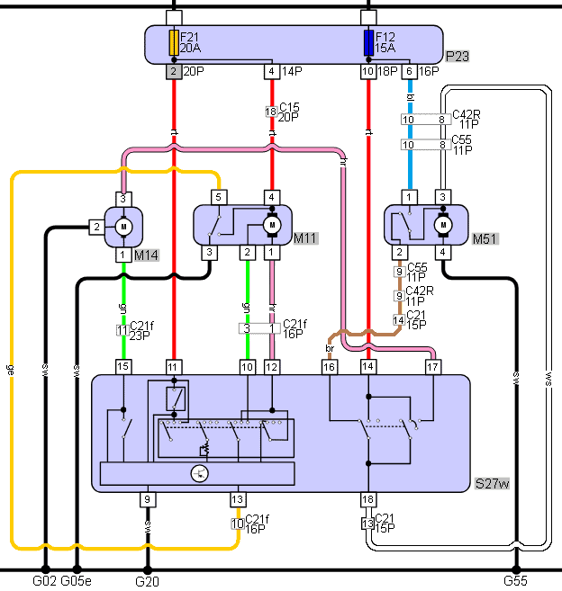
The wiring diagram below is based on the rear wiper motor of a Hyundai Getz. The wire colours (blue, brown, white and black) correspond to the colours in the car.
Numbers 1 to 4 in the diagram on the right and below show the pins of the connector through which the wiper motor is connected to the car’s wiring harness. The numbers and wire colours in both diagrams correspond. The diagram below was requested from HGS-data.com. In this, the rear wiper motor has the component code: M51.
In both diagrams it can be seen that the blue wire (pin 1 in the connector) is the constant positive wire from the fuse. The brown wire (pin 2) is responsible for rotating back to the zero position. In the diagram below, the contact plate is shown as a mechanical switch. The switched positive wire from the switch is connected to the white wire (pin 3). The black wire is the ground wire (pin 4) and is connected to a grounding point on the bodywork (G55).
In the rest position, the electric motor is short-circuited with ground; the white and brown wires are connected to each other via the contact disc.
Two-speed wiper motor:
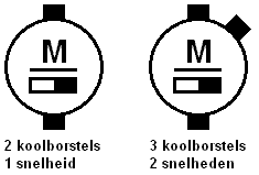
Up to now, only the single-speed wiper motor has been discussed. This is suitable for the rear window. The front wiper motor can often run at two different speeds, namely the normal speed that is used for both the intermittent mode (first switch position) and continuous wiping (second position), and the high speed (third position). Between the second and third positions of the wiper switch there is therefore a speed difference at which the electric motor runs. This is achieved by using multiple carbon brushes. In the single-speed wiper motor there are two carbon brushes; in the two-speed wiper motor there are three. In the image on the right, the symbols of a single-speed and a two-speed wiper motor are shown.
At the higher speed, fewer armature windings are engaged. The counter-electromotive force generated by the rotation of the armature is now smaller. Because less counter-voltage is generated, the armature, and therefore ultimately the entire electric motor, runs at a higher speed.
The diagram of the two-speed wiper motor is very similar to the diagram already discussed above. The wiper motor here is again switched on the positive side.
There are now three switch positions visible.
– Position 1: low speed, constant running.
– Position 2: high speed, constant running.
– Position 0: switch off, rotate back to initial position (zero position).
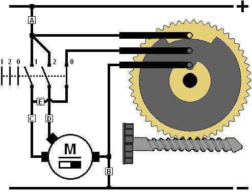
In the diagram on the right, the first position is switched on. This is the low speed.
Here position 2 is switched on. The motor now receives the positive supply via another carbon brush. There is now a lower counter-electromotive force in the electric motor, so the speed is higher than with the connection of the other carbon brush.
In this diagram, position 0 is selected. The motor is switched off, but first returns to the initial position. The contact plate connects sliding contacts A and B to each other, so that the wiper motor still has a supply voltage. When the contact plate has rotated 180 degrees further, the contact between sliding contacts A and B is interrupted, causing the supply voltage to disappear.
The operation of the contact plate and the sliding contacts is the same as with the single-speed wiper motor.
In this situation, the contact plate has rotated again, so that sliding contacts B and C now make contact with each other. The motor is now connected to ground on both sides. In this position, the wiper motor remains until it is switched on again.
LIN-bus controlled wiper motor:
The systems mentioned earlier use control voltages originating from the wiper switch. In modern cars, control via LIN-bus is increasingly being used. The control unit controls the wiper motor. Multiple inputs, from both the switch (S) and the rain / light sensor (RLS), provide a signal to the ECU to switch the wiper motor (RWM) on, to have it wipe at a different speed, or to switch it off.
The diagram shows the components that control the windscreen wiper motor.
The switch (S) is connected to the ECU by the three green wires. Via these wires, the position of the switch is transmitted.
So the switch has no direct connection to the RWM, as was the case with conventional control. The RLS receives its power supply (12 volts) from the ECU, its ground via a ground point, and sends its signal via the LIN bus wire to the other connected components. The RWM is controlled by a signal on the LIN bus. The control unit in the RWM (recognisable by the transistor symbol) provides the actual control of the electric motor.
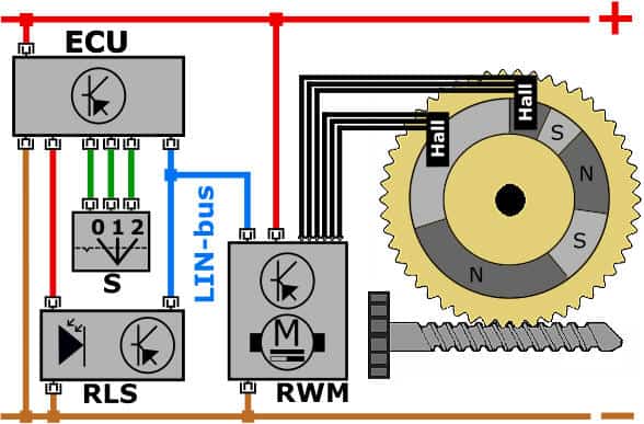
In a conventional windscreen wiper motor, the position of the conducting contact plate ensured movement to the park position. In a LIN bus controlled windscreen wiper motor, this contact plate has been replaced by a position disc and Hall sensors. The position of the position disc depends on the position of the plastic gear wheel, and therefore on the position of the wiper arm. The position disc is divided into a number of north and south poles (the N for North and the S for South). Because each north and south pole on the position disc has a different size, the control unit in the RWM can determine the exact position of the gear wheel by means of the Hall sensors. When the RLS or the switch ends the control of the windscreen wiper motor, the control unit in the RWM drives the electric motor until the position disc has reached the “park position”.
Advantages of this type of control are:
- PWM control makes it possible to operate at different speeds.
- The direction of rotation of the electric motor can be reversed; when rotating clockwise, the wiper arms move upwards and when rotating counterclockwise, the wiper arms move downwards. This allows a smaller installation space for the wiper mechanism.
- The park position can vary; by moving the wiper blades slightly upwards now and then, the rubber of the wiper blade tilts the other way. As a result, the wiper blade does not always rest on the windscreen in the same position. This has a positive effect on the service life of the wiper blade.
The LIN bus signal can be measured with an oscilloscope. The displayed scope image shows the communication between the ECU (the master) and the rain/light sensor and the windscreen wiper motor (the slaves).

On the page LIN-bus the structure of a LIN bus message is described. The communication of the wiper system is also described in detail and it is explained how faults in the LIN bus signal can be identified.
Related pages: